-
-

The buck puck is not compatible with the nano. It's used in place of resistors in a stunt saber. Wiring diagram for plecter boards are in the users manual.
-
Ah, you're absolutely right. I did a little more digging and I get that now.
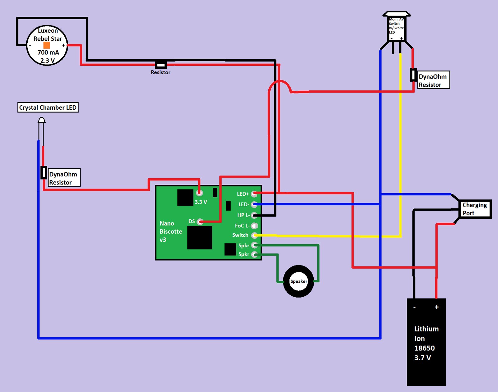
Okay, I switched some things around. Hopefully now it's better?

-
The returning negative from the LED goes to the pad marked HP-L in your diagram. FOC does not go to the switch and will not be usable with a single die. The negative to the switch also goes to its led and can be shared. Polarity of the switch is not important but but for its led it is. They are the pair marked + & -
-
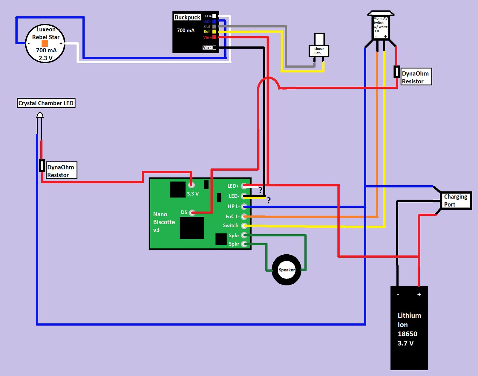
Ah, okay! I think I understand a little better now. I made some more changes to the diagram, let me know if I'm interpreting your words correctly.
An extra bonus to this is that my diagram is simplifying considerably each iteration. I really appreciate your expertise here. I'm still unsure about the battery-charge port-switch relationship. Should there be a negative lead coming from the switch to LED- on the NB?
Also, my switch is unmarked, it just has four terminals on it. I'll have to experiment to see which are for the LED and which are for the switch itself.
-
Part of the confusion here is your labels. LED+ and LED- should be BATTERY+ and BATTERY-. HP L- is LED-.
Your switch need one leg to the switch pad, the other goes to GND (BAT-).
 Posting Permissions
- You may not post new threads
- You may not post replies
- You may not post attachments
- You may not edit your posts
-
Forum Rules


 Reply With Quote


Bookmarks