So the red wire with the resistor (On the 3.7 V - 6 V Basic Set Up) is going to the positive lead on the led?


So the red wire with the resistor (On the 3.7 V - 6 V Basic Set Up) is going to the positive lead on the led?
I'm a kid, I don't know any better.
Originally Posted by cardcollector

Credit goes to Boj-Vaati Mau. This setup includes a buckpuck with accent LED.
Credit goes to skottsaber. This eliminates the Flash on clash and provides a nice flicker effect.
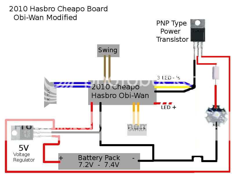
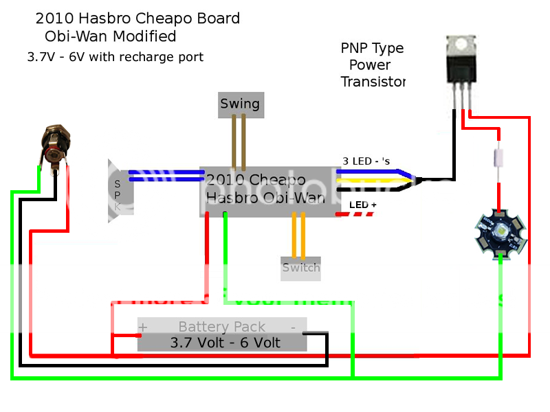
Please note that several diagrams poated throughout this thread are incorrect, they have the battery going to the collector, and the LED going to the emmitter. DO NOT wire them that way. you will only get 300-400 ma as opposed to 1000-1100ma wired as the diagrams above.
[/QUOTE]
Hi man! Please. What the value of resistance before the, Cree 5W royal blue LED with 4,5volt o TIP42C, to the best performance? I'm with the same project here. Can you help? Thanks a lot!
Marcc,
I didn't use a resistor on my build. Working so far.
You need to read the basics. It is all explained very clearly in the getting started forum. There are many many videos as well.
Try 500 ohm 3w resistor when in doubt.
Oh yeah! I didn't see others foruns! I'm sorry! Thanks a lot for your help! Rgds from Brazil!
OK I'm giving up/giving in to posting this question after hours of melting my brain.
It seems I can't figure out a simple "normally closed" situation with the semiconductors.
So the Hasbro main LED does the blinking thing. While I plan on using the speaker (-) output to the gate of a TIP42 to drive my main LED, I just want to use the onboard LED output with a MOSFET or what ever I need to have the light output reverse. So, when the board sends power to light the LED, I'd be using that as a trigger to turn OFF a circuit, and vice versa. This would result in a flash-on-clash signal that is off until the blinking (off pulses) turns it on.
I have spent hours reading about n and p-channel transistors, thrysistors for latching, FETs, pull-up and pull-down resistoring.....I am burnt out.
If this were an electromagnetic relay setup in my car I'd be done already.
I can't imagine someone hasn't done this already, but I also read practically all 90 pages of this thread to no avail.
I appreciate any input someone might have to entertain the idea. Please ask if clarification is needed as to what I'm talking about.
Thanks.
MTFBWY

It sounds like you are asking what is the opposite function of a TIP42, that would be a TIP41.
Thank you. So then the base gets connected to the LED (+) on the board?
I don't think accomplishes the goal though. That just changes the polarity needed at the base.
The collector and emitter need to be connected when NO current present at base, and not flowing when current present. I need a component that opens the switched circuit when getting current/voltage.
A depletion MOSFET perhaps?
Or a solid state relay?
http://www.mouser.com/ProductDetail/...zB6VnogQ%3D%3D
Last edited by NoSloppy; 04-19-2017 at 12:39 AM.
I found the following online. While it's pretty much pain english, can anyone apply it to this lightsaber application (hasbro board), such as the resistor values, or even better, a diagram (not schematic) of what this looks like? I can't put myself through anymore self-taught EE theory right now.
""To change the PNP behavior to act "normally closed", you could use a PNP transistor in a common-collector configuration. Connect the collector to ground, connect your load to the emitter and connect a shunt resistor from the transistors base to ground. This way, if there is no power to the base, the transistor is conducting, there-by grounding your load. If your input voltage to the transistor (at the base) is high, then the transistor cuts off the current flow, "disconnecting" the load.
also
You can bias a transistor of essentially any variety with a resistor to the base/gate that is small enough to turn the transistor solidly on (using the power you have to drive the circuit), and then have your control circuit provide the opposite voltage via a smaller (or zero-ohm) resistor. When the control circuit goes unpowered or is disconnected, the bias resistor is unchallenged and turns the transistor on.""
So I made this diagram from what I'm getting from that. What could the R value be? (The "shunt" )
Hasbro Obi Wan 2015 V1_NOT RIGHT copy.jpg
Last edited by NoSloppy; 04-19-2017 at 12:32 PM.
No Sloppy,
The only way to do that is with single pull/ double throw relay, the on/off signal from the blinking is too fast and the LED just stays on.
Alternatively the diagram skottsaber has with the speaker negative to the transistor gets rid of it all together. You can also put a resistor onto the speaker negative before the transistor to get a good balance.
Or you could put a seperate transistor/LED circuit off the speaker negative,the LED won't be as bright, but when the main LED is flashing, the speaker LED is still on/brighter.
Does that make any sense?
Thank you for your response and patience with me on this.
Yes, what you say makes sense. I understand the speaker neg option will be a constant somewhat flickery signal. That is what i plan to use for the main LED color.
However, I question what you said: "The only way to do that is with single pull/ double throw relay, the on/off signal from the blinking is too fast and the LED just stays on."
What makes you think that? Don't you think the response time on a transistor is surely fast enough to respond to the on/off blinking? I have made a 3 channel color mixer in another saber using potentiometers and p-channel mosfets. They are controlled by the LED Negative on a Nano Biscotte, and the flicker and flash on clash effects work no problem.
I'm looking to try anyway and from what I've learned, it should be possible by either setting up a PNP in a common-collector way (which I need clarification on for this application as asked above), or by using an NPN as suggested several times in this thread as being "the opposite" operation...normally closed and passing signal between collector and emitter when the Hasbro board LED shuts off, and not passing signal when the LED is on.
As best I can gather, the base pin gets tied to the collector, but whether PNP or NPN will determine whether pos or neg signal is used to trigger the base, and consequently which polarity is passed through the collector and emitter. Also I have no idea what resistance is needed on said "shunt" resistor between base and collector.
Holy cow this is ridiculous to put into text.
The quotes I posted above are from Google results on some electronics pages and describe how to invert the operation of the transistor, I just can't wrap my head around the practical application in this situation, and am hoping someone could clarify/define/edit the diagram I put up to make this work.
Thanks again.
 Posting Permissions

 Reply With Quote
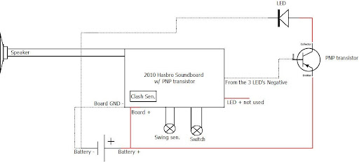


Bookmarks