


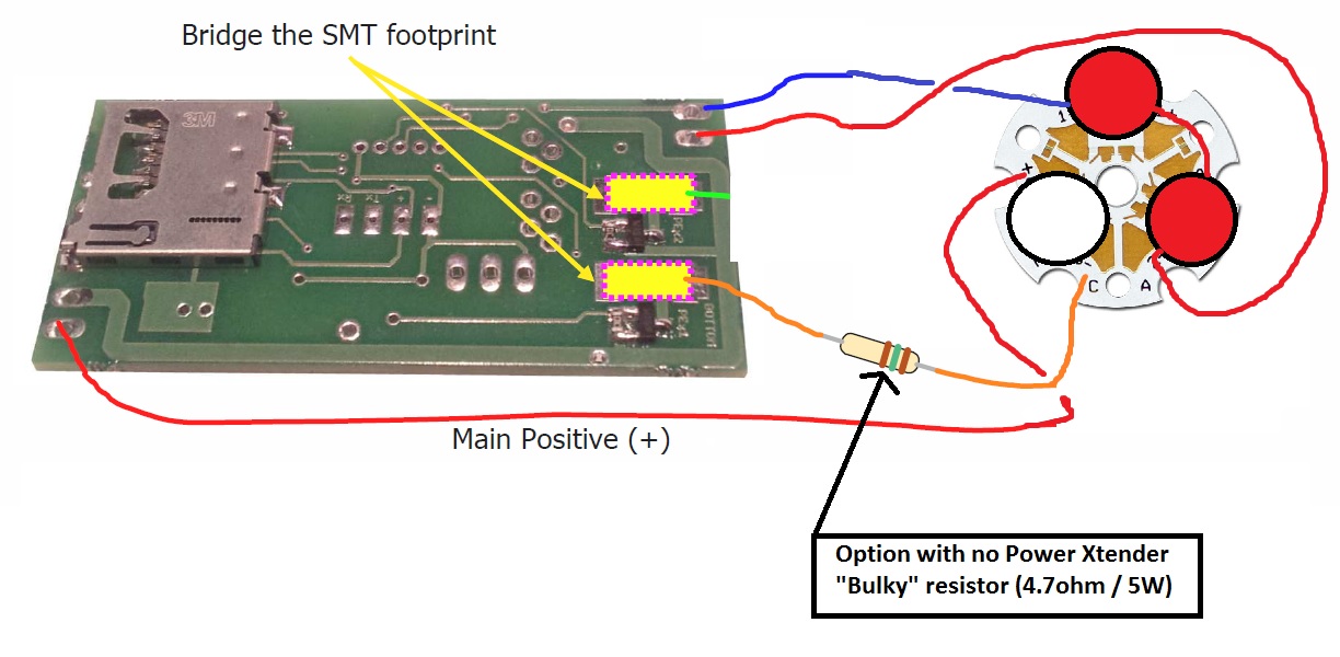
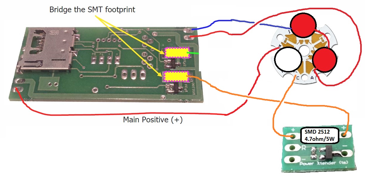
Not exactly. While that is how you do it (more or less), the picture you have is for the old PC v 2. You would use the picture in the manual on page 28 on the version 3 manual. You would bridge those two SMD pads and then using the picture on Page 29 as a reference. where you see the resistor, that is where the Power Extender would go, with your resistor. You would only need the one that is marked FoC1. In the Version 3 manual, Erv' seems to reverse using the (+) and (-) (it use to be the other way in older versions) so, you just need to make sure that the wire (with the resistor) is soldered from the FoC Pad to the (-) of the White LED.

 Reply With Quote


Bookmarks