Page 1 of 2 1 2 LastLast
Results 1 to 10 of 17

Thread: Resistor Question ..Nano biscotti and a Luxeon 3-up rb/rb/rb.

  1. #1

    Default Resistor Question ..Nano biscotti and a Luxeon 3-up rb/rb/rb.

    First let me say, sorry if this has been asked or if its a dumb question.
    I'm a bit uncertain and would like to get the advice of the pros before proceeding.

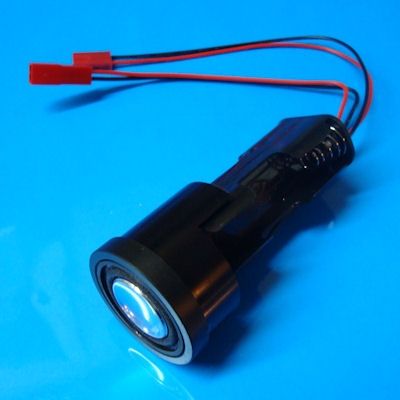
    I'm building a PVC saber and using NB card for sound.

    Power source is 2x14500 for a total of 7.4 volts.


    The led is a 3-up royal blue/royal blue/royal blue. This led is bridged/wired in serial.


    When calculating for the resistor for the led do I use the total VF for all 3 leds (10.2 vf) ..or just one? 3.4vf

    Also, Please advise if you think I need to make changes to some of the components as well.

    Thanks in advance.

    Albert

  2. #2

    Default

    Well, first off, the NB won't handle a 7.4V pack, it can only handle up to 5.5V.

    Your best bet is to use an 18650 3.7V battery. You can then wire 2 of the 3 dice in parallel and run them at 1A (1000 mA). That will be pretty bright. In that setup, the battery pack Vf is 3.7V and the LED Vf is 3.4. YOU would have to put a resistor on each (+) wire to each die you wire up.
    TCSS MODERATOR
    All n00bs READ these first (PLEASE)!!!:
    1. Forum Guidelines
    2. FJK’s “Down and Dirty” guide to Ohm’s Law

    "Yeah, yeah, I've heard it all before... you want blindingly bright, super loud, running 1138 blinkies off of the cheapest sound card you can find AND you want all of it to run on a battery the size of a dime, and run for a very, VERY long time. That one cracks me up every time..."
    My email: fjk_tcss@yahoo.com

  3. #3

    Default

    Quote Originally Posted by forgetful jedi knight View Post
    Well, first off, the NB won't handle a 7.4V pack, it can only handle up to 5.5V.

    Your best bet is to use an 18650 3.7V battery. You can then wire 2 of the 3 dice in parallel and run them at 1A (1000 mA). That will be pretty bright. In that setup, the battery pack Vf is 3.7V and the LED Vf is 3.4. YOU would have to put a resistor on each (+) wire to each die you wire up.
    Thank you, jedi

    I was more screwed up than I realized. lol

    Off to the store to look for some components. I appreciate your help very much.

    Albert

  4. #4

    Default

    Quote Originally Posted by forgetful jedi knight View Post
    Well, first off, the NB won't handle a 7.4V pack, it can only handle up to 5.5V.

    Your best bet is to use an 18650 3.7V battery. You can then wire 2 of the 3 dice in parallel and run them at 1A (1000 mA). That will be pretty bright. In that setup, the battery pack Vf is 3.7V and the LED Vf is 3.4. YOU would have to put a resistor on each (+) wire to each die you wire up.
    If he puts them in parallel, and then gives the pair 1000ma, each die will only get 500ma. If you calculate the resistor value for 2000ma, you'll be giving the two led's 1000ma each, and get a much better result.

    Got a question? Start Here. Have you tried the Thread Index yet? Most questions can be answered there.

  5. #5

    Default

    Quote Originally Posted by Jay-gon Jinn View Post
    If he puts them in parallel, and then gives the pair 1000ma, each die will only get 500ma. If you calculate the resistor value for 2000ma, you'll be giving the two led's 1000ma each, and get a much better result.
    He was suppose to give each DIE the 1000 ma. You are right though, I wasn't as clear as I could have been.
    TCSS MODERATOR
    All n00bs READ these first (PLEASE)!!!:
    1. Forum Guidelines
    2. FJK’s “Down and Dirty” guide to Ohm’s Law

    "Yeah, yeah, I've heard it all before... you want blindingly bright, super loud, running 1138 blinkies off of the cheapest sound card you can find AND you want all of it to run on a battery the size of a dime, and run for a very, VERY long time. That one cracks me up every time..."
    My email: fjk_tcss@yahoo.com

  6. #6
    Council Member
    Jedi Master
    FenderBender's Avatar
    Join Date
    Jul 2008
    Location
    Earth System - Rhode Island
    Posts
    1,531

    Default

    I would wire two 1ohm 2watt resistors in parallel to bring it down to .5ohm and let it ride full drive 3 up. That will blind you.

    If you're new, please take the time we all consider just as precious as you and READ!

    GET LATHED!

    Official BMF and LORD OF THE STRINGS

  7. #7

    Default

    For Series wiring, see http://led.linear1.org/led.wiz . It shows wiring in parallel with a 1 ohm 2 watt resistor for each die. Useful site for this typo of thing.

  8. #8
    Council Member
    Jedi Master
    FenderBender's Avatar
    Join Date
    Jul 2008
    Location
    Earth System - Rhode Island
    Posts
    1,531

    Default

    When you calculate based on the total MA usage, and not the needs of individual dice, you get like .00001 ohms which is next to zero. Normally, I'd say to not even use a resistor, but it will pull the voltage down too fast and also heat up the board transistor and you'll get mad false swings. A 2w 1 ohm on the set of three, or 2 of them wired in parallel (twist the leads together and solder) for .5ohm (brighter option), will work just fine. The LED vf and the source voltage are really close here, what you're trying to do is just keep them from drawing over the limit that the board will pass through, and to keep the battery voltage from dropping to fast.

    If you're new, please take the time we all consider just as precious as you and READ!

    GET LATHED!

    Official BMF and LORD OF THE STRINGS

  9. #9

    Default

    Fenderbender: Going back to the comment on a pair of 1ohm2Watt resistors in parallel allowing you to run it "full drive 3 up", are you referring to being able to run all 3 LEDs at 1000mA? I ask since I've been swearing over being limited to a total of 2000mA running parallel on both of my last 2 sabers, leading to a little less than 700mA per LED (the limit being due to not wanting to go over the 2000mA current limit Mr. Plecter put in as the maximum for the NB) and I'd love to run them brighter on future builds (both were gifts to friends scattered across Texas and Canada so I can't change those but...). My only frustration with the NB (I love the board otherwise, amazingly tough and incredibly versatile) has been the limit on current. I know that the Petit Crouton can get around it with the pex but not the NB. Any advice you can give is very much appreciated. Thanks!

  10. #10

    Default

    I believe the nano board is limited to 2000mA. You need to stay below that. As to what to use for resistors, follow the link I posted above and play with it. Tell it to output in a wiring diagram and you'll get a picture of what to put where.

Bookmarks

Posting Permissions

  • You may not post new threads
  • You may not post replies
  • You may not post attachments
  • You may not edit your posts
  •