


Hi, all.
I am finally in a position where I can begin practicing my wiring/soldering on some of the cheaper components (if I fry these, I'm not out so much money) and I thought I'd post the results of my first attempt. Before I continue, let me say that I have read and understand (I believe) the wiring diagrams and tutorials provided by the forum's stickies. I will also say that, just as I'm no electrician, I'm also no photographer. The picture supplied may not do you any good in critiquing my application.
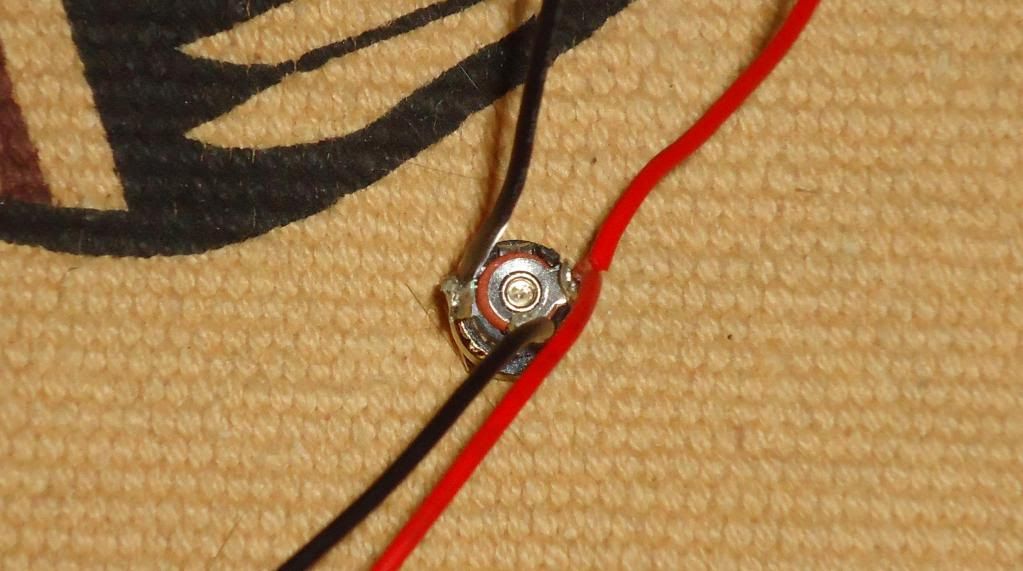
I began by selecting the recharge port for my initial experiment. I have a volt meter, so measuring whether I have successfully made contact without bridging anything should have been pretty easy. I looked up the diagram provided Corbin Das (Thank you, Corbin. Thank you forever.) and did the best I could.
It was my understanding that the port's positive (+) receives both the battery pack and the soundboard's positives (+), so I soldered the two positive wires together, then to the contact pin. I then soldered the battery pack's negative (-) wire to the central pin -the port's negative (-)- and the soundboard's negative (-) to the port's second negative (-), which is the last pin on the left. If the port is oriented with the center pin at the bottom, the right pin holds two red wires(+), the bottom pin holds one negative wire (-), and the left pin holds one negative wire (-).
If I read things right, the switches are wired directly to the board, in the corresponding holes. I believe the main and Aux share a common negative, but I'll have to reread the PCU manual. I'm not ready for switches yet, anyway.
When it was all wired up, the board input wires measured voltage without the plug, no voltage with it. I had voltage at the battery output side with the charger plugged into the port, no voltage at the battery without it. I just have to remember to either order a new charger, or ask Tim for a replacement connector, since I did a stupid and forgot that Tim orders custom chargers from Tenergy, not the stock model. I've got a recharge port plug with a plastic white connector and a battery charger with alligator clips. ~facepalm~
I chose to wire everything with the JSTs, simply because they're easy to connect and disconnect. My wiring scheme is consistent: Anything which outputs to a device is wired as a male JST. Anything which receives input from a device is wired as female. If every wiring connection is done in the same way, I can tell at a glance whether something is an input or output.
But...it works. I know it's an extremely simple procedure and just routine for all the experts, but I'm a total novice at this. I'm proud of it. I just can't believe I got it on the first try.
More as I get it.

 Reply With Quote


Bookmarks