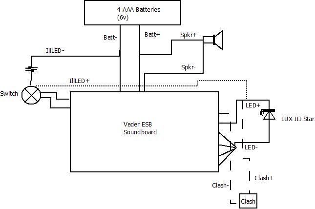
Ok I made the following diagram based a bunch of posts I've reviewed over the past day or so and wanted to check if I am correct or if there are issues with it.


Ok I made the following diagram based a bunch of posts I've reviewed over the past day or so and wanted to check if I am correct or if there are issues with it.

I usually take both + and - leads for the switch LED off of the main board outputs but I don't really see anything wrong with the way you have it.

If you're new, please take the time we all consider just as precious as you and READ!
GET LATHED!
Official BMF and LORD OF THE STRINGS
Do you need to use a resistor for the switch LED and what kind?
-Sidd-

That is easier, I'll change up the diagram. Got my Vader board in today and since the illuminated switch is on the way to the LED that will neaten things up.
Yes, for the ones that Tim sells (and most of the ones I've seen that'll fit) you need a 220ohm 1/4w resistor. Check the resistor chart in the store for your specific LED.
Bookmarks