-

 2nd Lightsaber - First with Sound
Greetings everyone. 
I've decided to begin work on my second lightsaber project (well; technically my third). My first saber was a stuntsaber; light but no sound. The second saber was one for a friend; he designed it and I assembled it for him (it was also a stuntsabor). For this build I would like to include sound in my design, and acquired a Mace Windu MR FX soundboard for just that.
I'm posting for two reasons:
1) To list the parts I believe I need and see if you, the veterans, can tell me if I'm missing anything (I don't want to screw up, of course).
2) To ask a few questions regarding the build that I'm a bit confused on.
So, on to the first reason; the list of parts.
- MHS Blade Holder style 18
- 8-32 x 1/4" button head screw
- Double ended male threaded connector
- 1.2" Double Female
- Hilt style 2 with guarded style switch hole
- MPS Pommel style 7
- MPS Insert style 6
- MPS Clip for Pommel
- DPDT Latching green illuminated switch
- Bezel for illuminated switches
- 8-32 x 13/32" Black Thumb Screw
- 1-1/2" x 12" Chrome sink tube
- Black machined button for Covertec clip
- 8-32 x 1/4" socket head
- Necessary powdercoating orders
- MR FX Mace Windu soundboard
- MHS speaker and battery holder
- 2 Wire quick connector
- Extra wire; just in case
- Necessary heatshrink
- I plan on either reusing the green Seoul P4 LED I already have installed in my stuntsaber or ordering another LED with the Seoul P4 Electronics Kit; probably the former.
I already have a tap and drill set for the 8-32 screws.
And a render of the saber in question, and as you can see it is heavily based on Qui-Gon Jinn's design. The total length will be 11". The covertec clip button is not there because I haven't decided where I want it yet.

So... what am I missing or what did I get wrong, because I'm sure there's something I've missed. 
So on to part 2; the questions.
I plan to wire everything similarly to how Jay-gon Jinn wired his CS-21 saber, and did not notice a resistor for the illuminated switch (which I will also be using). I'm confused because every other thread I read says that a resistor is needed for the illuminated switches. Is this not needed for an FX soundboard?
Will the 1-1/2" sink tube fit over the powdercoated MHS parts, because if not then that's a big problem for the design.
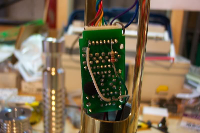
Finally a conundrum; I got the Mace Windu board off an eBay auction. However, it did NOT come with the multi-wire plug that I see in all other builds; it has the insert for that plug on the board, but the wires themselves are not there, so I do not see how I will be attaching the LED to the board. Does anyone know of a place where I can purchase one of these plugs?

Thank you for your time; any help you guys can give me would be appreciated.
Last edited by Hageshii01; 01-04-2010 at 07:27 PM.
-
-
When I say plug I mean the mass of wires that connect the LED and board together; the one where you have to connect a bunch of the wires together for the LED- and one wire for the LED+. You didn't have that either?
Fortunately the seller just responded to my question and is sending a replacement my way.
As for the 1.5 sink tube, I'll be sure to ask him if that is the case. Does he charge extra for that?
-
-
I apologize; I'm calling it a plug because I really have no idea what else to call it.
Look in that picture I have at the bottom of the first post; the part of the soundboard I circled with the rainbow of wires; that did not originally come with the soundboard when I bought it; I had no wires for the LED.
Fortunately the seller IS sending that part to me.
-
-
Unfortunately yes.
However I contacted the seller and he quickly replied and said that he had a spare part he would send to me, so that's all settled.
-
Council Member
Jedi Council Member


I didn't use a resistor on the illuminated switch in Cs-21 because it was a different switch than what Tim sells now. The led in it was rated for 12volts, so I didn't need a resistor with it.
Also, the chrome sink tubing that Tim sells will fit just fine over a powder coated part, I've done it a few times myself.
You also don't need that wiring harness connector to be able to use that soundboard. since it has a separate one for the clash and the motion sensors, all you need to do is remove that plastic plug, and solder wires in it's place.
-
I see, but since the seller will be sending the wiring harness connector (awesome; an actual name for me to use) I can use it if I prefer; correct?
So, assuming that I put together a quick wiring diagram of what I believe I'm supposed to do. I decided I'd like an LED indicator in place of where I have that thumb screw (it was cosmetic only), so that'll be included.

I feel like this is wrong. I have the switch connected to the LED like that because the resistor chart showed me that setup, but how accurate that is.....
Last edited by Hageshii01; 01-05-2010 at 11:02 AM.
-
 Posting Permissions
- You may not post new threads
- You may not post replies
- You may not post attachments
- You may not edit your posts
-
Forum Rules


 Reply With Quote


Bookmarks