Yes, thanks. Its a little bit confusing since I'm rusty, 1st electronics project in about 10 years.Originally Posted by Jedi-Loreen


Yes, thanks. Its a little bit confusing since I'm rusty, 1st electronics project in about 10 years.
Some progress:
My 1st order from TCSS shows up tomorrow hopefully but I'm working both days so get some things done in the evening.
Also, I acquired a Vader ESB Fx board so I had to get a latching AV illuminated switch and rethink the wiring diagram.
Two things I'm concerned about - first, since the orange III is 1400ma am I going to have enough juice to run it brightly with the Fx sound board? And I'm fairly sure I can run it directly from the board without a resistor now.
(Got the 2nd point figured out with the wiring thanks to a Do-Clo post from a few weeks ago)
Mapping out cuts for the shroud around the blade holder and choke and made some cuts into the grip area shroud which I need to work on some more.
Photos coming up tomorrow - brushing the shrouds for the grip and the blade holder tonight to hide some issues I created due to my below average dremel-fu.
Last edited by Dakarn; 01-09-2010 at 08:39 AM.
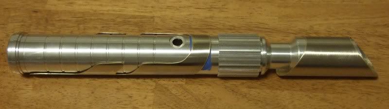
Updated photos with the finished bottom shroud, the arrival of my MHS pieces and a test fitting.
I ended up brushing the shrouds because of some marks I made with the dremel - my dremel-fu is weak. I like the look though, the top shroud still needs to be cut and brushed some more to better match the bottom one.
Onto the photos:
The MHS pieces arrive!
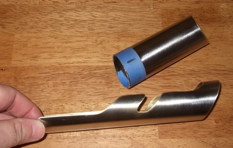
Brushed chrome shroud - 3/4 view
Test fitting - its about 3/4" too long so back to the cut off it goes.
Next up - finish the top shroud off and get the electronics together within the next few days.
Last edited by Dakarn; 01-12-2010 at 07:19 AM.
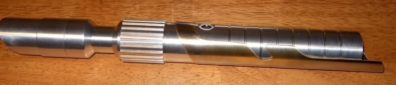
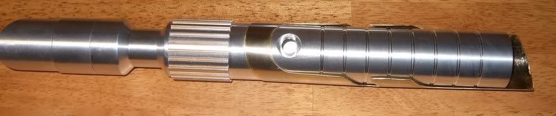
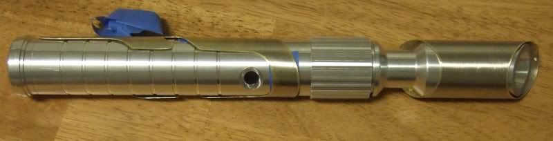
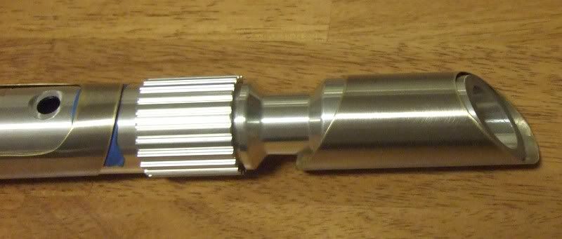
Got both of my overlays done! So it was test fitting time!
Top View
3/4 View
Close up of the Blade Holder Overlay
Next up - drilling and electronics. Going to use a step bit to open up the switch hole to 5/8" for the AV illuminated switch and bezel and then the wiring commences.
I'm tempted to drill it without a drill press but I think that's going to be a disaster.


Looks great so far. Keep up the good work and don't rush it. Take your time to make sure you don't make mistakes.
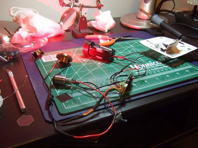
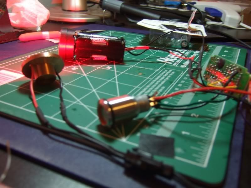
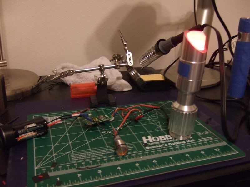
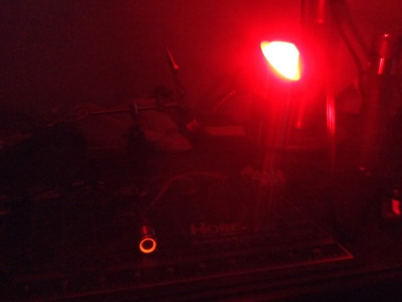
It lives!
Wired it up and worked on the 1st try. Forgot to wire in the resistor for the AV illuminated switch but it worked fine, going to do that tomorrow.
It's Alive!
The barely illuminated switch
Wiring
More Wiring
One question - the lens and lens holder are giving me fits. I know to cut off the tabs on the lens holder so it fits, but how do I mount the holder to the copper heat sink effectively?
Next up - wire in the resistor for the illuminated switch, buy a drill press and put some holes into the hilt then get it all actually into the hilt!

Hi, if these are all MHS parts, there is no need for any glue or stuff like that.
I got some videos on youtube where it's in there, in this topic : http://forums.thecustomsabershop.com...ead.php?t=9994
The lensholder is basically dropped into place on the copper heatsink, the copper heatsink is placed in the choke and then the emitter part holds everything tight into place when screwing that on. One tip : hold your finger through the emitter part and on the lens so you feel the pressure when screwing the emitter into place. You'll see.
"A Jedi Master always said this to each of his students before their first lesson: Cross an unfamiliar river without first discerning its depths and shallows, and you will drown in its currents without reaching your goal. Being a Jedi is no different. Identify the pitfalls and learn the proper path, or you fail the Order and sacrifice yourself to no good purpose."
Thanks! Just to add, the LED star solder points (not your wiring solder points) should be at a 90 degree angle to the mounting holes for the lens holder to fit properly according to a Jaygon and Loreen last night.
So I'm resoldering the LED this evening and adding the resister for the AV switch LED which I forgot in my excitement. Then finally drill the mounting points for the shrouds, get all that wiring inside the hilt and solder the AV switch leads to the switch.

its lookin good, can't wait to see more!!
Thanks, I can't wait either!
Just a quick update, shortened the wiring and resoldered the LED mounting last night. The lens fits ok, used some hot glue at the 2 mounting niches to hold it down, think I'm going with 10deg lenses from now on because of the fit issue.
I put in and then took out the resistor for the AV switch LED after reading the specs on the one I got - it doesn't need it.
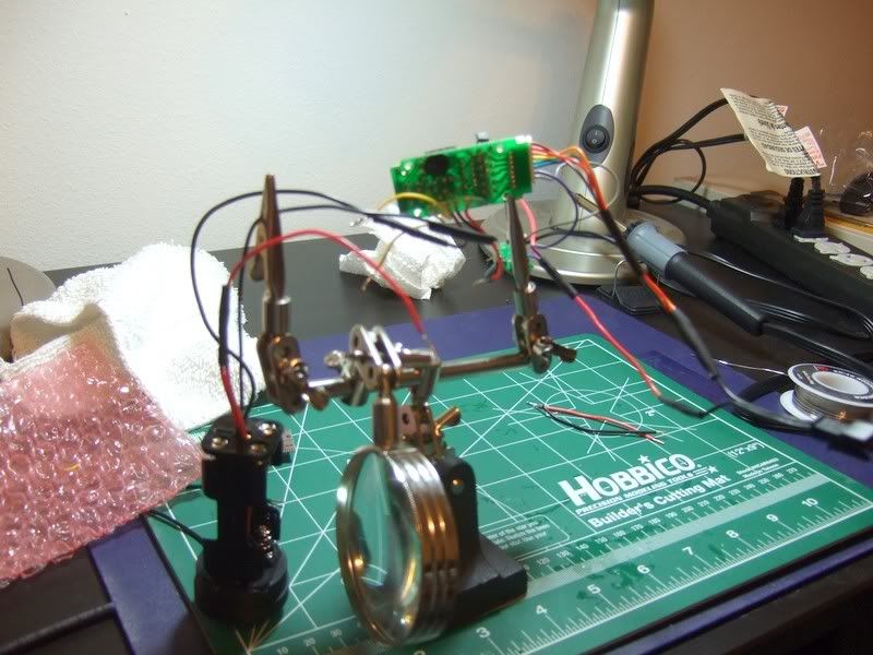
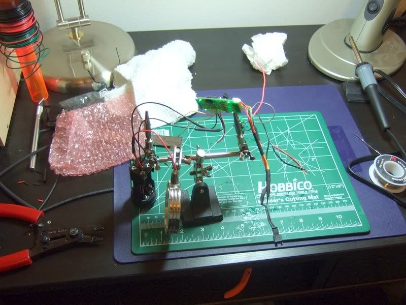
Soldered up some short leads on the switch to make it easier to work with then got everything setup and put the LED assembly in the holder:
Lights Out!
Also put the blade into the holder but forgot to get a photo - got the 1" heavy blade and its good but it needs some cellophane to even it out a bit.
Put the hilt together, wrapped it all in painter's tape and marked out my holes so I can drill and tap them this morning. Then I'll hot glue up the sound card sled, get it all mounted and it'll be done!
 Posting Permissions

 Reply With Quote
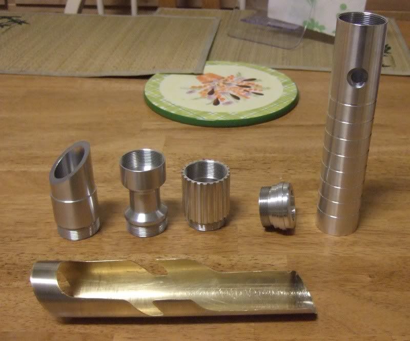

Bookmarks