Page 3 of 3 FirstFirst 1 2 3
Results 21 to 27 of 27

Thread: Shadar's "Mr. Green" (US 2.5 Custom)

  1. #21

    Default

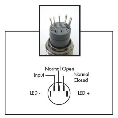
    I will have to check when i get home but i am 99.9% certain that when using this as a guide:


    that i specifically left the NC prong un-soldered and isolated via heatshrink...

    *edit* Now that i think of it, i believe the switch worked as normal before rewiring the accents... Just the LED didn't light up.

    *edit edit* I went home and checked and yes, the only prong not soldered is the Normally Closed, the others are wired up as stated in the image above so that cannot be the issue... i did find this here that i think will do the job nicely... i will see about getting it and fixing up my wiring, makes me wonder if the L1 pad is simply bad....
    Last edited by Shadar Al'Niende; 12-28-2009 at 06:07 PM.
    Every time Tim ships an order... an angel gets its wings


    "Just get one and go nuts, that's how this hobby works. Get stuff. Go nuts. Period." ~FenderBender~

  2. #22

    Default

    Quote Originally Posted by Jedi-Loreen View Post
    The end of a solder sucker (desolder pump) has a sort heat resistant plastic on the end, not rubber.

    I prefer using solder wick, also called desolder braid. Radio Shack has it.

    Here's a page about desoldering, using both methods:

    http://www.aaroncake.net/electronics/desolder.htm
    This was extremely informative.Thanks, J-Lo. I've been at this for more than two years, and I still learn something new every day. It had never even occurred to me that solder could be sucked away! Until now, when I've discovered that I've mis-soldered a multi-pin device to a PCB, I've either made an ugly mess trying to remove it or just started from scratch with new parts. It's great to be able to draw on the collective experience and knowledge of people like you who've been doing this for a decade or more.
    There's always a bigger fish.

  3. #23

    Default

    Thanks for all the information guys, it has been very helpful. I am in the process of wiring up a US 2.5 as well. I am forcing myself to be patience and take my time so I don't end up screwing up the board or having to replace anything. I bought the board first ... then the hilt ... now I'm not sure it will all fit ?? if I have trouble i will post pictures.

    Then again when the store opens back up I may just buy an MHS hilt from Tim. Which means of course starting my design over ..UGGH !! )
    “He's a friend from work.”

  4. #24

    Default

    Ok, quick update...

    The pads on the us 2.5 were indeed fried (i bought a multi-meter and checked...nada), so i had to change boards until this one can be repaired. I ended up ordering a MR FX Jedi board (Luke ANH 2005) this presented a few problems...

    1. US 2.5 can take >6v the Luke cannot (need new batt solution)
    2. Lux V green needs >6v to run properly (need new LED)
    3. US 2.5 uses a Momentary switch, Luke does not (need new switch)
    4. US 2.5 regulates v and mA to accents and main led, Luke does not (resistors)

    With all this in mind i had to go back to the drawing board with my battery solution.

    Having the hilt pre-drilled the way it was left few options for the change. I had to keep the same basic idea, but change the internals. First thing was first, what led/battery combo to use. There was no way i was going to replace a 2AA holder with much else other than a 4 AAA holder due to length restrictions or make a custom pack. I considered a custom pack which led me to the NiMH solution. I then looked at my options. I could do a pack with 5x NiMH's and get 6v, this would be optimal for the Luke. I set about looking for an LED with similar brightness to my LUX V and of course came across the P4 Green. It is driven quite well off 4v and 1A so a 4xAAA holder and the 1-1.2A that the Luke puts out would work well.

    *whew* battery and led solution solved. Now to tackle the switch and the resistors. I calculated the resistors needed thanks to Tim's calculator in the store here. When i initially ordered the green AV's were out of stock so i went elsewhere and paid $24+ for my Momentary switch (ouch...) Lucky for me Tim was in stock with the latching av's i wanted! I went back to my parts to make sure everything would work...

    CRAP!

    Without the board sitting on top of the battery pack (typical us 2.5/2AA holder setup) that left me needing 2 more inches for the board lengthwise... <insert infernal howl here...> So, i sat, and sat, and sat... Finally i realized that if i modified what i had done with my crystal chamber i could BARELY squeeze it all in (i am still worried that my cram-fu will not be sufficient) The board (opposite side of the header pins for the led neg) will sit under my recharge port by about .25 inches (reaaaaaaly tight sqeeze) and I will have to modify my battery pack a bit to allow the accent led wires to pass through properly for my crystal pommel... All this being said, i MAY have to end up wiring a custom pack ANYWAY...

    I will keep you all posted on how it goes!
    Every time Tim ships an order... an angel gets its wings


    "Just get one and go nuts, that's how this hobby works. Get stuff. Go nuts. Period." ~FenderBender~

  5. #25
    Jedi Council Member cardcollector's Avatar
    Join Date
    Jan 2009
    Location
    I am A proud American.
    Posts
    2,567
    Blog Entries
    3

    Default

    Well, I can't elp with all of those problems...

    But I do know you can just throw a 5v regulator in there and that should solve your power issue.
    Got a Question? There's a thread for that...
    ~Do what you can, with what you have, where you are.~Teddy Roosevelt

    SollusVir everywhere else... FXsabers, Youtube, etc...

  6. #26

    Default ...

    Did you ever get your saber fixed with the US 2.5? Hope you did.

  7. #27

    Default

    Ok...so quick update.

    This saber seriously tested my Cram-Fu. So much so, that the accent led is simply a no go in the pommel until i can figure out a way to alter my battery pack. For now I am just glad to say I have it done!

    I would have taken a picture of the wiring and a video for the bench test, but the wiring is not pretty due to all the Cram-Fu that was needed. having reverse sound, an illuminated AV, and a recharge port all in the forward portion of the hilt made not only fitting, but manuevering the wiring a PITB. Also, i ran out of Heatshrink (i think my son got a hold of it...) and had to use masking tape until i can get more.

    I will be getting my gallery pics up shortly, thanks for all the help and support folks!

    *EDIT: BAM... Pics are up!
    Last edited by Shadar Al'Niende; 03-26-2010 at 01:12 PM.
    Every time Tim ships an order... an angel gets its wings


    "Just get one and go nuts, that's how this hobby works. Get stuff. Go nuts. Period." ~FenderBender~

Bookmarks

Posting Permissions

  • You may not post new threads
  • You may not post replies
  • You may not post attachments
  • You may not edit your posts
  •