


The 4060 chip is a good choice for your led flashing needs. It wastes little power and it regulates current at about 15ma on the outputs so you don't need resistors in line with the leds. The setup I will show will be as simple as I can make it & will use the least amount of parts as possible. You can make more elaborate setups but we won't do that here.
The 4060 IC comes in a couple sizes. To save space & for a more shock resistant setup I will be using the surface mount version. For those new to surface mount components do not be afraid. They are not much harder to mount than axial lead stuff. I will try to convey some of the techniques that I use to make stuff.
Ok here is a diagram showing the basic circuit I will be using.
The way the 4060 works is R1 & C1 create a clock or on off pulse that makes the chip start working. The chip starts counting & turns the Q pins on & off at different speeds. The Q pins are numbered, the higher the number the slower they blink. C1 can be as small as small as 1000pf or as big as 1uf. R1 can be from 200k to 1megaohm. I will be using a .01uf capacitor & a 470kohm resistor.
For power we need at least 5 volts for the RC circuit to start working preferably 6 volts up to 14 volts. The reset pin resets the IC when power is applied & is grounded for normal operation. There are two examples of the ways that leds will be driven. One is the normal way with power from one of the Q pins on one lead & the other grounded. The second example is an led with both leads to different Q pins. To make the best use of this type of connection one would connect the positive lead of an led to a faster blinking pin & the negative lead to a slower blinking pin to get a heart beat type of inter mitten blinking. There are a lot of different ways to connect leds. The rate at which they blink will depend on power supply voltage & the RC components.
The parts I am using can easily be found online. For bread board I am using a common type with rows of pads for several different types of chip foot prints. For the CD4060BC the pins are 1.27mm apart & 4.75mm from one row of pins to another. This is a common size & can be found at an electronics store. I found mine at Fry's. The LEDs I will use are PLCC surface mount 20ma high output.
As the Q pins have a big difference in how fast or slow they flash some will be too fast or slow to use. About half of the rates are at a speed that is usable. Also since the rate at which they blink are multiples of each other they will always be in sync in a way. To make mine more random and alive looking I will use two 4060 chips to drive 9 LEDs & sort of mix up the order in how they are connected. To make them run at different speeds 1 R1 is 470k ohm & the other is 1 mega ohm. T 1 meg resistor chip will run at about half the speed of the other.
Piece of breadboard with two 4060s & LEDs on different piece of breadboard.
The bottom
Please forgive the sloppy soldering I reworked the boards several times. If you can make it out there is a 10uf ceramic cap on the bottom from power to ground. It's not absolutely necessary but it is always good to have one there to protect the ICs. The two small sets rectangle parts on top are the RC circuits. A good size part to start with is 0805 size. The parts I used are a little smaller than that. Using a board with a ground plane on the bottom makes wiring easier.
Don't be frightened by the size of the parts. To put it together you will need an iron with a fairly small tip,wire for power, rework wire (very fine green wire in completely assembled pic) ,9V battery for testing, thin rosin core solder, tweezers, & solder wick so you can remove excess solder when needed. And of course you need the main components.
First tin the pads on the breadboard by putting the iron on the pad for a second until it accepts the solder. When pads are lightly tinned grab chip with tweezers and line pins up with pads. While putting light pressure on chip hold iron sideways so you can heat up a few pins at the same time. Now slide iron back & fourth across the pins till it seats. Do this until both sides are seated & pins are lined up with pads. If it gets crooked don't worry just apply more solder & try again. When you get it straight use solder wick (copper weave that absorbs solder) to remove excess solder. When putting the 0805 resistors & capacitors on tin the board holes first, grab the part with tweezers put a dab of solder on your iron & touch both sides of the part to put a tiny bit of solder on them. Now technique is similar than with chip but smaller, hold part with tweezers align, apply light pressure & move iron fairly quickly from one end of the part to the other until it seats flat on the board. When you get the chip & the RC circuit on the board connect it to the 9V battery & with a 20ma led you can start playing around with the different configs. Don't forget to ground the reset pin. At this point I identified configs I liked & drew a diagram. The rest is regular old stripping wires & soldering into holes on the board unless you want to stack two boards on a small package like below. To apply the rework wire cut a small piece, hold it in about the position it will be on the board, cut to length & leave enough for the bent ends to go in the holes. Straighten wire, put on a flat surface, with exacto knife lightly apply pressure & roll wire in fingers, roll wire under knife for 1 or 2 turns then scrape insulation off & repeat. You will need to thread the wire so to speak using mostly tweezers.To attach one board to another I grabbed an axial lead part & threaded the lead through unused holes on each board & soldered.
Completed setup
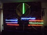
Glory pic. Its alive
Not sure why but the blue & green leds are a lot brighter than yellow & orange. Blues & greens are blinding even under driven.
Well not super easy but doable with some time & patience. I don't have a movie but I must say I'm satisfied with the performance of it.
Well I hope that is enough info for one to make one for themselves. If I left anything out or there are questions just ask.
Movie


 Reply With Quote


 TCSS the #1 Part supplier of


Bookmarks