


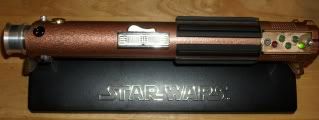
Here's the promised photo. I think it should not be difficult to decipher.
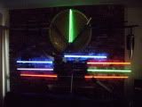
I will probably use a 4aaa pack (4.8v), and will have to make a common positive lead from the battery pack to the sound board and the LED. (As it is, the EL driver is wired to get 9v.) You may be able to see that the yellow leads from the switch both lead to the EL driver. (The yellow wire in the central pair of posts is joined to the positive lead from the battery pack, the yellow wire from the upper/forward pair of posts was attached directly to the EL driver board.)
Any suggestions?


 Reply With Quote
") For that, I'll have to wait for my Darth Maul conversion kit to arrive from TCSS. In the meantime, I'm going to try to find some way to make those red and green decorative "lights" on the side of the hilt actually light up. It'll have to be a pretty compact solution, because it will have to fit between the inner wall of the hilt and the aluminum tube of the conversion kit.
For that, I'll have to wait for my Darth Maul conversion kit to arrive from TCSS. In the meantime, I'm going to try to find some way to make those red and green decorative "lights" on the side of the hilt actually light up. It'll have to be a pretty compact solution, because it will have to fit between the inner wall of the hilt and the aluminum tube of the conversion kit.


 I have a feeling that thick wire set-up has something to do with shielding the wires from the electromagnetic noise generated by the EL film tube the wires pass through in the original setup. Jedi Loreen might understand this better.


Bookmarks