Page 2 of 2 FirstFirst 1 2
Results 11 to 19 of 19

Thread: Pulse LED using 555 timer

  1. #11

    Default

    Quote Originally Posted by astromech_kuhns View Post
    WOW. um, i took two red LED's and set them on the same circuit and gave them a different return path i think is what it was, and then when putting them on a switch, i was able to make them blink or stay on, and the knob i used would make one be brighter than the other while the other would go dimmer, not quite off, just very dim.
    Hmm. Well, that went over my head.

    Quote Originally Posted by astromech_kuhns View Post
    so let me get this correct, you are wanting to take a rebel RGB and have one side blue and the other red, then, once the clash happens you want them to switch sides of color, so the one that was once blue is now red and the other way around?
    It's a double saber, Darth Maul style, so I am using two LedEngin RGBAs. When one is red, the other should be blue. On clash (the clash sensor being a kind of momentary OFF-(ON) switch), I need both LEDs to switch colors, so that the one that was red becomes blue, and the one that was blue becomes red. It may be easier to visualize if you think of it as four LEDs (two red, two blue--the green and amber will not be used). At all times, two are on and two are off. The 555 timer will (I'm hoping) reverse the on-off state of all four. I hope that makes sense.

    Quote Originally Posted by astromech_kuhns View Post
    i could go back to school tomorrow, when im there, with my camera and if i have extra time i will look into this for you as well as upload a picture of the circuit that we used and put it on a bread board and work to create the circuit again and see what i can come up with.

    will work to help!
    I would be eternally grateful if you could do that for me, and maybe make a simple wiring diagram. Thanks in advance!
    There's always a bigger fish.

  2. #12

    Default

    I have one of these working for a 7.2v system if anyone is interested in resistor values and such for that voltage i can post those details.
    Good judgment comes from experience. Experience comes from bad judgment. -Jim Horning

    The beatings will continue until morale improves. -KMFDM "Free your hate"

  3. #13

    Default

    Quote Originally Posted by Jagahati View Post
    I have one of these working for a 7.2v system if anyone is interested in resistor values and such for that voltage i can post those details.
    Yes, please do. Two Li-Ion 14500s has recently become my setup of choice. Thanks.
    There's always a bigger fish.

  4. #14

    Default

    To do what It sounds like you want to do all you need is a relay on the leds you want to switch. One set terminals for normal operation & the on set for circuit being flashed.

  5. #15

    Default

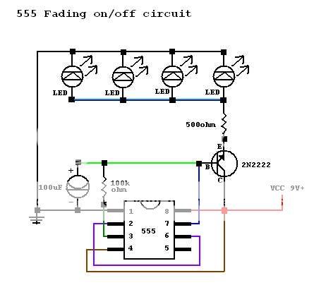
    Ok here is the schematic that is posted on instructables by "PCMOFO".


    Ok there are a few significant changes from the diagram.

    First I am using an "Ultra Bright" LED not 4 "Super Brights".

    Second I am using a 7.2V source NOT a 9v source

    Thirdly in place of the 500 ohm resistor I am using a 100 ohm resistor. This resistor is there to insure you don't fry the LED. Use your meter and test the voltage coming across this point to decide what value of resistor you need to protect your LED of choice.

    Lastly in place of the 100k ohm resistor I am using a 22k ohm resistor. This is because of the difference in the load from the 4 super bright LED's to my one ultra bright and the difference in voltage from the original design. This is the resistor to "fiddle with" if you want a slower or faster flash rate. a value between 10k and 100k should give you very different results in output .

    Hope this helps somebody.
    Good judgment comes from experience. Experience comes from bad judgment. -Jim Horning

    The beatings will continue until morale improves. -KMFDM "Free your hate"

  6. #16

    Default

    Quote Originally Posted by Sunrider View Post
    To do what It sounds like you want to do all you need is a relay on the leds you want to switch. One set terminals for normal operation & the on set for circuit being flashed.
    Sorry, Sunrider, I don't follow you.
    Quote Originally Posted by Jagahati View Post
    Ok here is the schematic that is posted on instructables by "PCMOFO".


    Ok there are a few significant changes from the diagram.

    First I am using an "Ultra Bright" LED not 4 "Super Brights".

    Second I am using a 7.2V source NOT a 9v source

    Thirdly in place of the 500 ohm resistor I am using a 100 ohm resistor. This resistor is there to insure you don't fry the LED. Use your meter and test the voltage coming across this point to decide what value of resistor you need to protect your LED of choice.

    Lastly in place of the 100k ohm resistor I am using a 22k ohm resistor. This is because of the difference in the load from the 4 super bright LED's to my one ultra bright and the difference in voltage from the original design. This is the resistor to "fiddle with" if you want a slower or faster flash rate. a value between 10k and 100k should give you very different results in output .

    Hope this helps somebody.
    It definitely helps. Thanks a million!
    There's always a bigger fish.

  7. #17

    Default

    Here is a short low quality rather horribly done video. But it should be adequate to show the slow fade on and off effect that I was able to get this circuit to do.

    Good judgment comes from experience. Experience comes from bad judgment. -Jim Horning

    The beatings will continue until morale improves. -KMFDM "Free your hate"

  8. #18

    Default

    Quote Originally Posted by Jagahati View Post
    Here is a short low quality rather horribly done video. But it should be adequate to show the slow fade on and off effect that I was able to get this circuit to do.
    That is sweet. What are the specs (mA, forward voltage, mcd) of the LED you used?
    There's always a bigger fish.

  9. #19

    Default

    Here you are. But for the most part I use these LED interchangeably with a few others. But this is a dang good guess.

    Technical Specifications from Datasheet:
    Intensity max (typ.) : 5000mcd (3200 mcd)
    Viewing Angle: 20°
    Wavelength (peak): 470nm
    Forward Voltage: 3,5V
    LED Current (If): 20mA
    Housing: waterclear
    Material: GaN/SiC
    Operating Temperature: -40°C - 80°C
    Good judgment comes from experience. Experience comes from bad judgment. -Jim Horning

    The beatings will continue until morale improves. -KMFDM "Free your hate"

Bookmarks

Posting Permissions

  • You may not post new threads
  • You may not post replies
  • You may not post attachments
  • You may not edit your posts
  •