Results 1 to 10 of 27

Thread: Joe Jedi Wiring Help Needed (big time)

Hybrid View

Previous Post Previous Post   Next Post Next Post
  1. #1

    Default Joe Jedi Wiring Help Needed (big time)

    Hello all.

    My joe jedi board arrived this morning and..I'm not sure what the previous owner was doing.

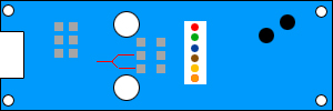
    I can't figure out based on existing diagrams floating around what to do here.

    Specifically...

    What is the power (+ and -) connection here?
    Which is the speaker connection?
    Which is the power switch connector?

    I'm nominally going to just use this as a sound board and not use it for driving a LED at all (maybe an accent down the road) but for now just use it in tandum with a resitor driven setup and if need be down the road the more advanced wiring diagram using a DPDT and all.

    Here are the pics:

    Underside:


    Clash:


    Color selector side?
    Momma in law: If this printer keeps printing the same thing I'm going to spit nickles!

    Me: if you start spitting nickles I'm coming over with a bucket!

  2. #2

    Default

    Ok, I believe I've figured it out based on another thread.

    VCC = power + (to battery + and speaker +)
    ground = power -
    spk = speaker -

    I'll have to use the DPDT to switch it and the LED on.
    Momma in law: If this printer keeps printing the same thing I'm going to spit nickles!

    Me: if you start spitting nickles I'm coming over with a bucket!

  3. #3

    Default

    looks like he used 'speaker' wire for the questions you had on speaker/+/-


    looks like the switch was taken off..however you can use th eunderside of the board:


    I would also suggest you check out this diagram:
    http://www.thecustomsabershop.com/wi...er/wiring.aspx

    under the misc. diagrams tab.. (theres only two currently)

    but this will deal with the 616 board set-up with DPDT switch and using a buck puck (much better solution)..also using the diode(s) so you do NOT loose the power down sound..

  4. #4

    Default

    Are we sure this handles 4aaa?
    I wired switch leads to a latching switch (push on/off) and not getting anything from the board.
    Could be dead..was sold as is but claimed to be working. Wondering if I'm doing something wrong or what.
    Momma in law: If this printer keeps printing the same thing I'm going to spit nickles!

    Me: if you start spitting nickles I'm coming over with a bucket!

  5. #5

    Default

    I believe it does.. not more than 6V...

    you can always try a smaller pack to be safe..

    could be he sold you a bad board too..

  6. #6

    Default

    I think its a dud.
    I double checked my wiring (did reverse the + - on the batt somehow..was using two 9v connectors so that may be lol), but still..

    switched speakers
    switched bat packs
    switched switches

    no dice.
    Momma in law: If this printer keeps printing the same thing I'm going to spit nickles!

    Me: if you start spitting nickles I'm coming over with a bucket!

  7. #7

    Default

    Quote Originally Posted by xl97 View Post
    looks like he used 'speaker' wire for the questions you had on speaker/+/-


    looks like the switch was taken off..however you can use th eunderside of the board:


    I would also suggest you check out this diagram:
    http://www.thecustomsabershop.com/wi...er/wiring.aspx

    under the misc. diagrams tab.. (theres only two currently)

    but this will deal with the 616 board set-up with DPDT switch and using a buck puck (much better solution)..also using the diode(s) so you do NOT loose the power down sound..
    Hey Xl on the mock up of the board you have done, on the reverse you have two little red lines. Are this showing the two pins you need to attach the LED to on the reverse of the original switch?
    Obi-Wan: "If you spent as much time practicing your saber techniques as you did your wit, you'd rival Master Yoda as a swordsman"

    Anakin: " I thought I already did"

    Obi-Wan: "Only in your mind, my very young apprentice"


  8. #8

    Default

    huh?


    I believe those are the two solder pads to use or your main switch..

    the current slider switch on the board is ONLY for changing between JEDI/SITH sounds (and changing the color of the led....but your not using that tri-color led...nor using the board to drive an LED)

Bookmarks

Posting Permissions

  • You may not post new threads
  • You may not post replies
  • You may not post attachments
  • You may not edit your posts
  •