


WALL OF TEXT VERSION
Hey guys.
Don't know if anyone else had run into this problem before.
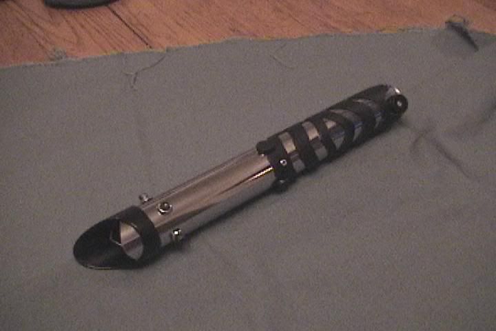
Basically I draw out my shroud designs on a piece of graph paper and then wrap that around the sink tube I plan to cut up and use it as a pattern.
The problem with doing it this way is a problem of angles on rounded surfaces. A 45 Degree angle on the pattern turns into a sloping and curved cut when translated onto the 3 dimensional surface of the tube.
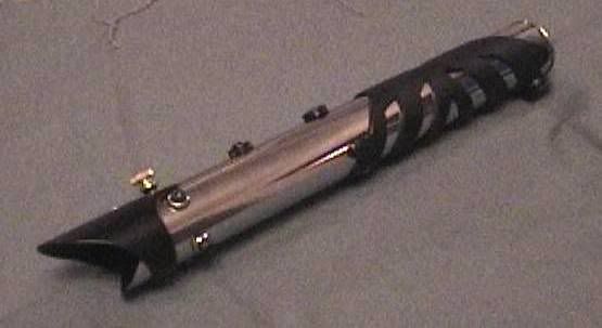
While this look may be OK if it is what you are after it is not desirable if you want to make nice clean angled cuts like those on some MHS pieces or like is done on the traditional Vader Saber.
It seems that the normal way to accomplish these cuts is to just use a miter box and a hack saw. While this works I was after a more controllable and more easily planned effect. That way I can plan the whole thing on graph paper and make a graph paper or card stock mock-up of the piece before i start cutting. This way I get a better feel for what I am doing before I do it and can more easily plan for things like screw holes switch locations cut-out sections etc.
At first I was trying to freehand these curves with relatively good results but not as crisp and precise as I would have liked.
Then after quite a bit of looking and trying to make my brain remember the math I am sure is involved in this problem I stumbled upon this:
Tube coping Calculator
If i set diameter of the second pipe to as large as it will go (10") then i get a very neat very precise pattern for cutting the sink tube with my Dremel to get the desired effect.
This works well IMO. does anyone else have a better or easier solution (that doesn't involve owning a C&C Mill and $1000 CAD software)?
Hope this helps somebody else.
TLDR VERSION
Check the link out. This lets you make 2d patterns for 3d cuts that look nice.
Tube Coping Calculator

 Reply With Quote


Bookmarks