Page 2 of 2 FirstFirst 1 2
Results 11 to 20 of 20

Thread: wiring 'weirdness'..

  1. #11

    Default

    "the 'new' switch is soldered to the bottom of the 616 board..bypassing the onboard switch.. which the switch isnt there..its just the 'socket/connector' of where the onboard switch used to be.."

    That may be your problem. If I am reading this right it sounds like you took the switch out.

    Its been a while since I messed with my 616 and cant remember what the other pins do on the factory switch.

    Now I cant really see how that can be the problem since you would think if you can bypass the switch with it off then the other pins aren't used but without being able to measure and actually see what the other pins do I am just guessing.

    Still if you have the switch you might want to solder it back in and test again.

  2. #12

    Default

    when I got this 616 board.. the orignal 'switch/button' wasnt with it.. just the 'connector/socket' still soldered on the board.

    wouldnt that make the 616 board NOT work at all.. as far as I can tell (now that the battery is charged to eliminate the sound stutter/skip problem).. the 616 is working as it should. (as it is wired up to be)

    its the LED that is opposite of what 'should' be happening..

    I expect:

    I hit the switch.. the sound comes on...power on (and it does).. I hit switch again..and sound goes off..power down (and it does)..

    however- when I 'power down'..the LED comes on..and it off when the sound is on!

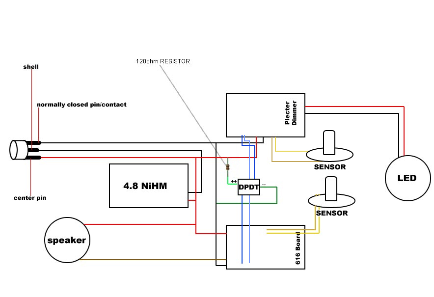
    normally I would just think I had soldered each circuit to the wrong poles.. but thats not the case.. (if the diagram supplied for the switch is correct)

    the switch is soldered/wired up just like the diagram(s) show..

  3. #13

    Default

    First I would not shear the clash sensors between to two boards. Even though they are powered from the same power source it could cause problems. I would use one of these. Run power to you clash sensor then have the switch out put activate this than you have two seperate out puts to use for each board. I know you don't have the clash hooked up now and that is not what is causing your problem but I thought I would pass this on.
    It appears to me that the Dimer board switch input is working backwards. You turn on the mr the dimer turns off the LED and vies a versa. I would just work with the switch and the dimer circuit first as a standalone circuit. Iron it out then add the MR. The switch seam to be the right one for the job. I didn't like some of the wording on the cut sheet though. Normal ON 1-2, 4-5. push off 2-3, 5-6. (that sounds good) but then they state Normal On 1-2, 4-5. Push on 3-4, 5-6. That should be Normal Off 1-2, 4-5. Push on 3-4, 5-6. Just reads funny, that's a funny switch "Now you funny too"

  4. #14

    Default

    thanks for the reply grayven-

    yeah the 'double use' of the sensor is really just to be a test.. to see if it could be used.. I could possibly just use another clash sensor all together.. (or use your link you provided)

    I had the dimmer set up in a circuit all by itself.. originally prior to re-charge port, the addition of the 616 and this switch.. (I was just usin a slider switch)

    my 'gut' is saying its this new switch... I suppose before I desolder everything and isolate the dimmer circuit with this 'new switch' I could swap out for a DPDT slider and see if anything changes.

    if that failes I'll seperate the dmmer with this new slider and add in from there.

    to touch on the comment about the:
    Normal ON 1-2, 4-5. push off 2-3, 5-6. (that sounds good) but then they state Normal On 1-2, 4-5. Push on 3-4, 5-6. That should be Normal Off 1-2, 4-5. Push on 3-4, 5-6
    that has thrown me a few times as well

    also-

    PB613A is the latching type I have

    PB613B is for the momentary type you can order (same style)


    Im seriouly tapped for space in this thing/build being as the switch is in the middle...

    craddle on top and bottom of the switch 'holder' LOL

    Thanks for the link.....

  5. #15
    Council Member
    Jedi Council Member
    Rhyen Skytracker's Avatar
    Join Date
    Feb 2009
    Location
    Covington, GA
    Posts
    2,550

    Default

    I have had cut sheets to be wrong. You may want to ohm out the switch to double check the cut sheet.

    Live long and...I mean May the force be with you. http://saberconcepts.50.forumer.com/index.php

  6. #16

    Default

    update:

    wired in a new heavy duty slider switch.. same issues..


    616 works as it should.. dimmer is opposite of what the switch is telling it to do..LOL

  7. #17

    Default

    Quote Originally Posted by xl97 View Post
    update:

    wired in a new heavy duty slider switch.. same issues..


    616 works as it should.. dimmer is opposite of what the switch is telling it to do..LOL
    Have you emailed erv yet?

  8. #18

    Default

    nope..Im going to break the dimmer into its OWN circuit today and test it again..then I'll email Erv...

  9. #19

    Default

    took driver/dimmer out of equation..ran it on its own...

    and it does the same thing.. when I slide switch "ON".... it doesnt power led on..when I slide switch "OFF".. the led comes on..


    emailed erv.. so I guess Im just waiting..

    after some snooping around on ervs site.. I see mention of a MR compatible version and a small link to some diagrams..

    1.) looks like the switch wiring is different than in my diagram.. (piggy backing off the MR switch leads)

    2.) looks as if you CAN piggy back both boards to 1 clash sensor.. (which is cool..since Im not sure I even have room to fit another in anywhere..LOL)


    http://www.plecterlabs.com/Media/Doc...wanMRboard.jpg


    it also looks as if you do NOT apply power/battery pack to EACH board? the one above shows it like you 'do' the one below shows it piggy backed with the MR?

    like in this diagram?
    http://www.plecterlabs.com/Media/Doc...MrBoard002.jpg

    Im starting to wonder what 'version' I was sold? the connection needs to be CLOSED for it to be off.. when the on/off circuit is OPEN...the LED is "ON"..


    I suppose I could just wire one side of the switch 'backwards/opposite' LOL


    :P
    Last edited by xl97; 05-09-2009 at 05:53 PM.

  10. #20

    Default

    just to update the thread..

    there are two VERSIONS of the Plecter Dimmer/Driver

    1.) an MR compatible version
    &
    2.) a 'regular' version

    the MR version can be wired TO the MR board to (I believe) power it, and also share the clash sensor..

    the regular version can NOT

    also the dimmer works like, CLOSING the connection/circuit turns the LED OFF.. while breaking the circuit turns the LED OFF..

    which is opposite of MR/616 boards..etc (or regular LED/power connection)

    so wiring the Plecter Driver opposite of the 616 board on the DPDT switch should work fine.

    still dont think sharing the clash sensor will work.. and I may need to 'find' another one..

    but I'll still give it a try..

    just some info on the Plecter Dimmer/Driver board...

    correct diagram:
    Last edited by xl97; 05-13-2009 at 03:18 PM.

Bookmarks

Posting Permissions

  • You may not post new threads
  • You may not post replies
  • You may not post attachments
  • You may not edit your posts
  •