Page 1 of 2 1 2 LastLast
Results 1 to 10 of 18

Thread: Touch Switch Tutorial

  1. #1

    Default Touch Switch Tutorial

    Disclaimer: I assume that the reader understands Ohm's law, knows the basics of electronics and knows how to read a schematic. I am not responsible if you do not take appropriate measures to ensure your safety. WEAR SAFETY GLASSES!!! Please do not attempt this project if you do not fully understand why this circuit works and what each part does.
    For those that want to have a resistance touch switch(and then 3 more!), here's an easy way to do it FOR UNDER $10!
    (Cost from my local electronics store $7.54)
    Step 1: Acquire the components
    (I assume you will already own the necessary tools to solder and strip wires)
    You will need:
    1 - 10uF 16V Electrolytic Capacitor
    2 - 100K 1/4W Resistors (R1, R2)
    1 - 10M 1/4W Resistor (R3)
    1 - 4011 CMOS NAND Gate IC

    (or it's equivalent - I am using a Quad 2 Input NAND Gate[4011BPC])
    DO NOT purchases an SMT type component unless you have either a lot of determination and a high level of soldering skill. SMT components are components that are meant for Surface Mounting. They are extremely small and hard to solder with a regular soldering iron.
    Step 2:
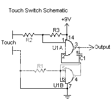
    Read and comprehend the schematic!

    Step 3:
    Solder and/or use your breadboard!
    Step 4:
    Be amazed!

    Alright, here's how it went.
    I put everything down on my project table, kind of just shoved the other stuff to the side. YOU should keep your table neat and organized!


    Now having a good knowledge of electronics from my robotics courses I took way back when I was a Padawan, I got right to the soldering!


    Nearly done with the pesky and super tiny NAND Gate
    DON'T BUY SMT COMPONENTS!!!

    This is why! Your soldering iron tip is the same size as the component itself!!!


    Then you plug everything into the breadboard, hook up a multimeter to see that it's so far so good.


    And finally, you grin and pump your fist in the air (don't hit the fluorescent tube lights above you though) and yell loudly that it works!


    Also, the reason it didn't output 9V, but rather 8.1V is this:

    Battery only gave out 8.1V!

    Now you have your very own touch switch. Hide those wires where you will so you turn your saber on with 'the Force'!

    Note: You only need to solder up pins 1-7 and 14
    I didn't pay enough attention and ended up soldering the others as well, at the risk of overheating my NAND gate.

    Hope you enjoy making your own touch switches, and if anyone has questions or needs help when trying it themselves, I would be happy to help!
    Last edited by Thaxos; 07-08-2009 at 07:57 PM. Reason: Resistor Specifying

  2. #2

    Default

    Sticky this for me, please? I put it in the Thread Index - LM <-- OMG TEH HAX!

    For those that don't understand but want to:
    Use Google and;
    Learn soldering, how to breadboard, multimeter use
    Learn Ohm's Law, understand NAND gates, capacitors, resistors
    Then come back and read it again.
    Last edited by Thaxos; 04-14-2009 at 08:45 PM. Reason: Lord Maul is teh haxor!

  3. #3

    Default soic

    sparkfun has a SOIC to DIP converter. It lets you solder the surface mount chip onto the board so that you have easier access to the pins. I am trying it with a LED segment driver chip that I got. It was not through hole as I was hoping for. I tried soldering wires directly onto a surface mount chip and found that it was nearly impossible because of the tight spacing. Congratulations on actually doing it.

  4. #4

    Default

    Quote Originally Posted by swear000 View Post
    sparkfun has a SOIC to DIP converter. It lets you solder the surface mount chip onto the board so that you have easier access to the pins. I am trying it with a LED segment driver chip that I got. It was not through hole as I was hoping for. I tried soldering wires directly onto a surface mount chip and found that it was nearly impossible because of the tight spacing. Congratulations on actually doing it.
    Haha thanks!
    I considered buying one of those boards, but I felt overconfident and so I headed home first. Then I realized my soldering tip was the size of the component.

    Basically, I tinned the wires, left a minute blob on the end, heated it slightly above the pin, then lowered it down and let the solder flow.
    Very tricky. Had to de-solder several times due to bridging.

  5. #5
    Sith Minion mihunai's Avatar
    Join Date
    Mar 2009
    Location
    The Netherlands
    Posts
    449

    Default

    when does this switch activate?
    when you touch your saber?
    i would really appreciate it if you tried to explain how this thing works, when assembled...

    mTm

  6. #6
    Council Member
    Jedi Master
    Obi-Dar Ke-Gnomie's Avatar
    Join Date
    Jul 2007
    Location
    Ontario, Canada
    Posts
    1,578

    Default

    I hate to be critical here. It's great that you put this tutorial together, but some of the pictures are too blurry to see what you did. Is there any way you could take sharper pictures? I'm sure there will be people that would love to see details on how to do this.

    Try mounting the camera on a tripod and using the close-up/macro/flower setting.

    I'm not putting you down, just trying to be helpful.


  7. #7

    Default

    Quote Originally Posted by mihunai View Post
    when does this switch activate?
    when you touch your saber?
    i would really appreciate it if you tried to explain how this thing works, when assembled...

    mTm
    in the next to the last picture you see him touching two wires with his hand. You would want to connect those two wires up to something for you to touch...like two pins close together on the saber hidden in the grip or something (isolated from the metal of the saber).

    Good work...its been a long time (around 18 years or so) since I dealt with this stuff in school.

  8. #8

    Default

    There's really not much more to see, you'd just see the wires clearer. My camera is not the greatest Gnomie.

    Yeah Zook has the right idea, and I'll bet you could hook up one electrode to the hilt itself, and run several wires off the other to various well hidden spots on the hilt so that touching the hilt and any of those wires would activate it.

    I will be making a single electrode touch switch (capacitance) which will simply require the person to touch it once to turn it on.

  9. #9

    Default

    Quote Originally Posted by Thaxos View Post
    I will be making a single electrode touch switch (capacitance) which will simply require the person to touch it once to turn it on.
    So it will behave like a latching switch?

  10. #10

    Default

    Quote Originally Posted by jtong77 View Post
    So it will behave like a latching switch?
    Wow, sorry it took so long to revisit here and answer you, didn't know you had posted a question.
    This one works as momentary, I've yet to build the other type which would behave like a latching switch.

Bookmarks

Posting Permissions

  • You may not post new threads
  • You may not post replies
  • You may not post attachments
  • You may not edit your posts
  •