Page 1 of 4 1 2 3 ... LastLast
Results 1 to 10 of 40

Thread: Here are some pics of one of the new hasbro sound boards

  1. #1

    Default Here are some pics of one of the new hasbro sound boards

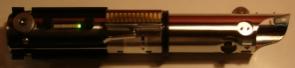
    These are some pics I just took of the sound board from the clone wars build your own lightsaber kit. I haven't removed the board yet, so I apologize for the angles. Take a look and see how you guys would wire it. It has a total of 9 LED's 3 green, 3 blue, and 3 red that are wired to the top of the board. It also has wires running from the back of the board to the crystal chamber which houses switched that are used to select each color & sound combo. If there are any specific pics or other details you guys would like while I have it apart, just let me know and I'll do my best to help.
    Attached Images Attached Images
    Last edited by samurai_rob; 11-13-2008 at 02:31 PM.
    "You've failed, Your Highness. I am a JEDI, like my father before me..."

    -Luke Skywalker, ROTJ

  2. #2

    Default

    Well it seems kind of obvious that the black wires are to the speakers.

    Red and black to the battery as usual. if there are 9 LEDs and each color combo is covered, then there should be at least 3 leads to the different LED combos from the switches. There should be one common or ground, that usually is the black wire but sometimes they use the red as common and wire the ground to the switches instead.

    Just see which color wires are coming from the switches, that should give you an idea of which color is for which LED. This is your LED drive current. If you combine those 3 wires you'll get a current that should be able to drive your LED.

    EDIT> Looking at the close up pic, you can see the leads labeled. VCC is your main supply voltage (from battery), GND is your ground to the battery. Then you have the red blue and green + wires that are your 3 LED supply voltages. GND1 is your ground to the LEDs.

    White is going to switch 2. can't really make out the other labels clearly.
    Last edited by MoonDragn; 11-13-2008 at 02:41 PM.

  3. #3

    Default

    Whoa! Thats a new setup!

    It looks like the top most board is like a driver, with the speaker housing a board with flash on clash, motion and sound???
    Momma in law: If this printer keeps printing the same thing I'm going to spit nickles!

    Me: if you start spitting nickles I'm coming over with a bucket!

  4. #4

    Default

    Yeah, the sound is great for the price, but it may be a little too much for my first saber. may buy a force action vader and use it to start with.
    "You've failed, Your Highness. I am a JEDI, like my father before me..."

    -Luke Skywalker, ROTJ

  5. #5

    Default board

    The clone wars build your own lightsaber kit looks nice. I am almost wondering if two of three LED wires could be used to drive accent LEDs. It also looks nice because it is a small board.

    The force action vader has a good card. I don't think it drives the Luxeon to it's full potential. It works but looks dim in comparison with other blades I have seen.

  6. #6

    Default

    I'm gonna use a 1000ma buck puck for a driver and was gonna use one of the cards just for sound. I don't really care about clash and flash on this build. Maybe later I'll invest in Corbin's driver board and then in one of the high-end cards like US or CF when I get more comfortable wiring.
    "You've failed, Your Highness. I am a JEDI, like my father before me..."

    -Luke Skywalker, ROTJ

  7. #7

    Default

    By the way, the little gray nub on the left side of pic 2 is the switch. It appears to be made directly into the board. Do you think it would work if you leave that switch in the on position and wired an on-off switch between the battery and the board?
    "You've failed, Your Highness. I am a JEDI, like my father before me..."

    -Luke Skywalker, ROTJ

  8. #8

    Default

    Quote Originally Posted by samurai_rob View Post
    By the way, the little gray nub on the left side of pic 2 is the switch. It appears to be made directly into the board. Do you think it would work if you leave that switch in the on position and wired an on-off switch between the battery and the board?
    I have the same board and from what I can figure that's a built in momentary switch and it needs to be used to turn on the board, a separate switch wouldn't do anything, I've been trying to solder an external switch directly from the strips under the rubber switch. I also attempted trying to mount it with a film canister close to the surface using the plastic button that originally came with the hilt, but it became a n issue unless you can anchor the unit.

  9. #9

    Default

    That's what I was afraid of. Anybody know how makototsia got around this?
    "You've failed, Your Highness. I am a JEDI, like my father before me..."

    -Luke Skywalker, ROTJ

  10. #10

    Default

    PM him, he probably removed the built in switch

Bookmarks

Posting Permissions

  • You may not post new threads
  • You may not post replies
  • You may not post attachments
  • You may not edit your posts
  •