Page 1 of 4 1 2 3 ... LastLast
Results 1 to 10 of 38

Thread: Corbin's NEW driver

  1. #1

    Default Corbin's NEW driver

    Hi all.
    I just wanted to let folks know that I have a new driver out. It's essentially the same as the first driver, but with a much smaller package and a couple extra abilities.....

    First off, YES....they will be available here at TCSS. There IS a bit of a price increase though. Tim can verify, but I believe they'll be $50.00 each.

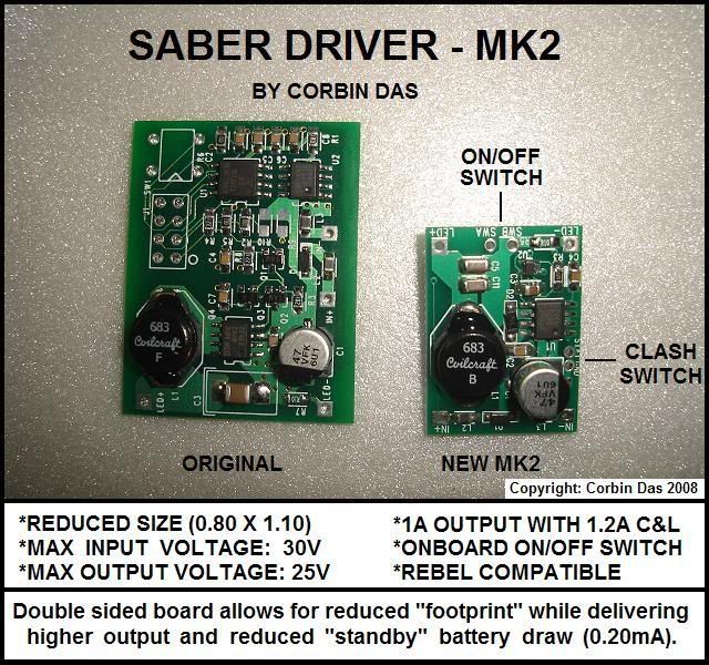
    The old driver board was 1.25" wide by 1.625" long. Not bad, but as you know, space inside a saber runs out REALLY QUICKLY, so the smaller, the better. The new drivers are only 0.8" wide by 1.1" long. That's a reduction of over 30%.


    A new feature this board has is static shimmer. Basically, once you turn the saber on, the blade will ramp up, then have a slight shimmer to it. The flash on impact and lockup option is still there, but the blade will have a static shimmer as well. It really helps the blade feel more "alive". I hope to be posting a video shortly, though the camera's frame rate probably won't really capture the shimmer like you'd see in person.

    Also, the driver will handle up to 30V input now and up to 25V output. That means if you wanted to run a few Luxeons in series (Rebel), the driver will have no problem with it. Though not tested with those 10 watt LEDs yet, their requirements fall within the capabilities of this driver.

    So, increased power in a smaller package. Not too bad.


    Corbin


    Stay tuned......
    Last edited by Corbin_Das; 05-20-2008 at 06:09 PM. Reason: Updated picture

  2. #2
    Council Member
    Sith Lord
    Lord Maul's Avatar
    Join Date
    Jun 2006
    Location
    Seattle area, Washington
    Posts
    5,169

    Default

    SWEET! That thing is tiny. No more sanding to make it fit in MHS hilts. What is the current output of it? 1000 mA just like the old version?
    Aluke123 on every other forum - Old grumpy moderator here

    Thread Index, The Saber Building Dictionary, and The Basic Saber-Build Tutorial - Read Them!

  3. #3

    Default

    Hi Maul
    The current output is the same as the original, 1000mA, with impact flash and lockup surging the output to between 1.2 and 1.5A.

    Corbin

  4. #4

    Default

    To bad you couldn't have a 3 position switch on the board selecting 700ma, 1a, or 1.5ma.

    But still that's awesome. you got that going alot quicker than last we talked about it. It still works with Mr and hasbro boards right? do you still need an extra clash sensor? can you use a C&L button with an mr board unlike with the last driver?

    Yes lots and lots of questions I have and more I will have when I remember them.

    Edit: Oh and are there gonna be 2 versions like before? the momentary and latching versions.
    Last edited by Hasid Lafre; 05-05-2008 at 09:21 PM.
    Any intelligent fool can make things bigger and more complex. - Albert Einstein

    Reaganomics not Obamanomics


  5. #5

    Default

    OoOOOhhh..I Likey! That should go nicely with a SW-616 board. WIll we have to wire a 2nd clash sensor like before with the MR boards? Same type of wiring schematic?

    This will do nicley!! I'm going with an Amber LUX III for my next saber with a 616 soundcard and then your board with shimmer and FOC, and I won't have to worry about pucks or resistors. (Just have to make sure to keep it under 6V so I don't fry the 616 board).

    Count me in!!!

    Hasid:

    You beat me to the punch on some of the questions>>LOL>> Good point about the C&L button (any sound with lockup??) I think that someone will have to get a new MR diagram out there once these are released. Since the CF sell like fire, Ultra boards, umm yeah.......the 616 boards are a hot ticket and I'm sure many members will be interested in using the new Corbin board with a MR 616 soundboard.
    Last edited by Dark Navel; 05-05-2008 at 09:27 PM.

  6. #6

    Default

    Hi guys
    This driver will act the same as the last one in terms of requiring a separate clash sensor. I've seen folks use a common clash sensor with some FX models, but I'm not sure how well that worked. You would be crossing currents from 2 different boards and that might make things act screwy.
    This is not a sound board, it makes no sound when you do the lockup. It simply flashes and shimmers the blade. If you have a DPDT momentary switch hooked up for the C&L button and tie that to the clash sensor of the FX board, I suppose you could get an impact noise, but the impact of the blades striking each other would do that anyway at the beginning of the lockup.
    I agree that a switch to choose the amperage would be nice. At this point, we were looking at more power in a smaller package. I suspect a user programable driver would probably have you use the C&L switch like an Aux button to run through a programming menu, but we're not there yet.


    Corbin

  7. #7

    Default

    Yeah, Well iam happy that its smaller now, much smaller it seems, will it fit on top of a 4AA flat pack?

    So corbin where could one find clash sensors? without having to dismantle other things like a hasbro.
    Any intelligent fool can make things bigger and more complex. - Albert Einstein

    Reaganomics not Obamanomics


  8. #8

    Default

    I understand about the sound issue. Hasid, I have found those sensors in many different items. It helps that I have a little girl to help me out. The toys she doesn't use anymore are chock full of these things.

    The rubber balls that light up when they impact something, her shoes that have small lights in them evrytime her foot impacted the ground while running, a hoola hoop that had three seperate chambers that would light up when she hooped etc. I think I may even have a diagram on how to make one.

    Let me look. Found it:
    Last edited by Dark Navel; 05-05-2008 at 09:51 PM.

  9. #9

    Default

    Well I really lioked the one that corbin got for me, man that sensor was the best and it was tiny as hell.
    Any intelligent fool can make things bigger and more complex. - Albert Einstein

    Reaganomics not Obamanomics


  10. #10

    Default

    Hi again
    I haven't tried setting it on a AAA pack, since I don't use them very often, but I'm thinking that it WOULD fit. Just measure the pack and figure 0.80" would be needed to fit the driver in place. Understand that the hieght of the components on the driver board would affect the areas you could fit the battery pack with the board in place.
    I haven't measured the thickness of it, but it uses some of the same components, so I think it's about the same.


    Corbin

Tags for this Thread

Bookmarks

Posting Permissions

  • You may not post new threads
  • You may not post replies
  • You may not post attachments
  • You may not edit your posts
  •