I just got a Graflexshop red button switch that I need to assemble but the button falls through the housing, anyone have a clue how I should put this together?


I just got a Graflexshop red button switch that I need to assemble but the button falls through the housing, anyone have a clue how I should put this together?


Sometimes graflex parts that are stock from a graflex can be different than the replica ones. Do you mean a blade graflex button or the activation swich? Hope that helps!

Hes talking about the switch one.
IIRC the red button attaches to the switch, then you afix the switch to the hilt and then the "cap" is afixed to the switch or something to that effect.
Iam just going by memory cause I remember someone else had this problem and that was close to the solution.
Any intelligent fool can make things bigger and more complex. - Albert Einstein
Reaganomics not Obamanomics


The switches at the graflex shop are intended to be mounted on a perfboard or pcb. If you don't want to mount all of the electronics right there under the button, or if you are using a manufactured board that you cannot attach the button to directly, you can always just cut a small section of perfboard to mount the button to, then mount the perfboard to the outside of the saber with a screw.

Hi guys
Depending on which switch setup you got, I can probably help you with this. I originally designed and sold the needed components to TGS for the switch integrated red button. It's been something I've been doing on my own for a few years now.
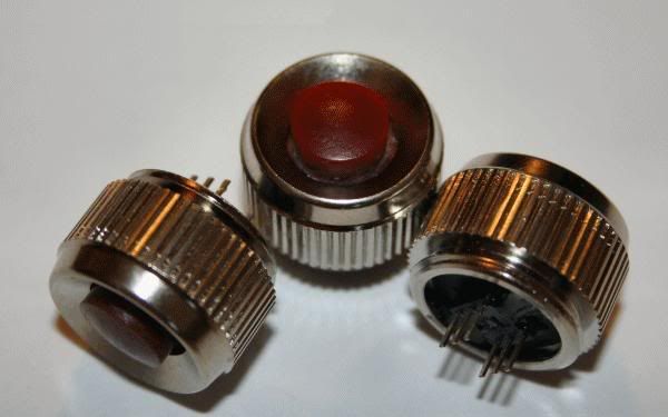
The actual red button part looks like this:
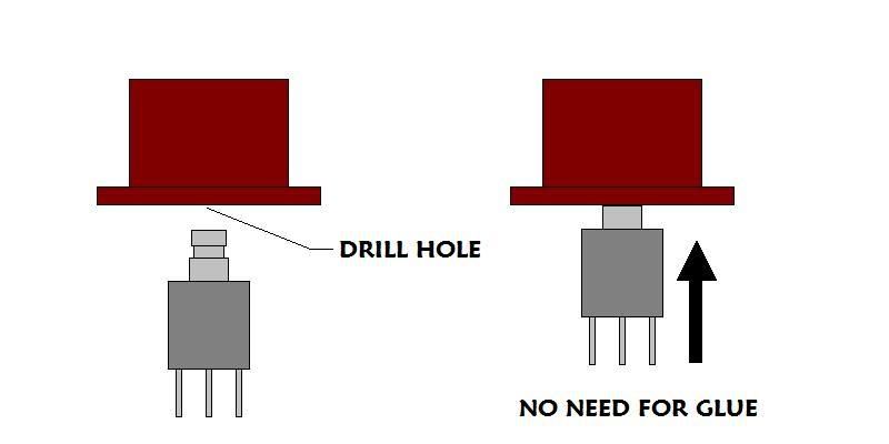
The kit should have come with a very small DPDT pushbutton switch and a black rubber washer with a square-ish hole in the center. What you have to do is take a drill or a dremil and make a small hole in the bottom of the red button piece. NOT ALL THE WAY THROUGH. Just a small hole that the plunger of the switch can fit up into (tightly). Don't make the hole so big that the plunger sits in it freely. What you want is for the head of the plunger to "snap" into the hole, effectively making the red button a part of the plunger.
I'd suggest getting a smaller drill or dremil bit than you need and use it to drill a hole in the center of the bottom of the red button. Then use the bit to open the hole up until you can JUST squeeze the plunger tip into there. Make sure not to let the plunger go into the hole so deeply that the square housing of the switch bottoms out against the bottom of the red button. You need there to be enough room for the switch to work.
Once that's done, take that black rubber washer and put it over the body of the switch so that the pins stick out one side and the rest of the switch and red button are on the other. Like this:
Then you just slide the entire setup into the bottom of the chrome bezel. You'll need to get the edges of the washer inside the bezel past the inner lip that's there. You'll want the washer to set a little inside the bezel and not flush with the bottom.
After you get it in there, mix up a small amount of 2 part epoxy. Take your bezel switch assembly and set it red button down on something that will keep it level. Any type of thing with a large enough hole for the red button to fit through works well.
You then take a toothpick or pencil or similar narrow tipped item, and gather up some mixed epoxy. You CAREFULLY let it drip off the toothpick and onto the washer. Be careful not to coat the pins on the bottom of the switch and don't let it overflow over the edges of the bezel. You don't need very much epoxy. Just enough to coat the washer and the bottom of the switch.
Let everything sit there until the epoxy is dry. It should look like this:
There are 6 pins coming out the bottom of the switch (2 sets of 3). Each set of 3 is its own independent circuit, completely isolated from the other. Power goes into the center pin and depending on if the plunger is up or down, power then flows to one pin or the other. This type of setup will allow you to control 2 different voltage for something like an FX board and a separate Luxeon driver, or a resonator motor, or whatever.
I hope this helps.
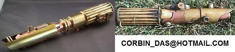
Corbin Das
Last edited by Corbin_Das; 02-17-2008 at 03:22 AM. Reason: Spelling

didn't know it was you initially behind this red button project. Too bad TGS does not have a tutorial. I've requesting that to him when first purchasing there, and got not answer. No that it's difficult, but the kit came with parts I actually didn't need to fit it in. I couldn't use the washer, and ended up by hot gluing the switch totally. I think my ESB is still like that. I also had to lathe the red part of the button otherwise I couldn't get the latching switch latching properly.
At the end, I had to install the switch in the graflex head first, then slide in my modified blade mount (TCSS version). Ah... early days.
I like this red button but I prefer now using the stock one, like I did on my very first graflex. I'm using ultra tiny mom switches for that purpose, since now with the anti power off system of crystal focus, it's just fine to use momentary (this is the main reason I've used this red button kit in the past).
Just littles thoughts, Corbin, if you can convince TCSS to put a user's manual / assembly instruction on his website, that would be great. At TCSS too.
Erv'
Props Electronics
http://www.plecterlabs.com
Hi Erv'
Yeah, it was I who started doing those Graflex buttons originally. I ended up running out of the individual parts though (the red button, bezel, etc). I had Ace machine a red button "master" so I could have more cast, but with the discovery of newer and smaller momentary switches, I, like you, have just used stock Graflex buttons with a driver capable of using a momentary on/off input. It's easier than trying to keep the wires from twisting while screwing the bezel down, like the original model.
Still, for a direct driven Graflex, or something using a Graflex switch where you need a latching mechanism, these little beauties are nice. A bit labor intensive to assemble, but nice.
Perhaps if there's an interest, I'll look into having more parts made up and assembling some of these things. Like I said, they're nice, they just take a while to assemble.
I assume you meant "The Graflex Shop" and not TCSS twice.Originally Posted by erv


Hey Corbin,
Any way you can show us a tutorial on converting a graflex button to use with a momentary switch?
Scott
Just put a tiny (thin) mom switch on your blade holder (but do it so it doesn't short out on the blade holder) and rig the stock button so it will push the mom switch. You'll need to glue something to the bottom of the stock button since it doesn't come down far enough. Then you can slide your blade holder out without having to disconnect the switch.
Question: Who sells replica red buttons that are just like the original?
Jedi-Diah: Tim just started selling graflex red buttons http://www.thecustomsabershop.com/Re...tton-P329.aspx
 Posting Permissions

 Reply With Quote


Bookmarks