Page 11 of 24 FirstFirst ... 9 10 11 12 13 21 ... LastLast
Results 101 to 110 of 235

Thread: Hasbro sound module schematics and discussions

  1. #101

    Default

    Thank you for the suggestions all. I will add the film tomorrow and post results.

    Matt, I am using the 4AAA holder/speaker mount sold in the store to power things. I am using the resistor Tim sent me with my kit. And I got a 5v relay from RadioShack.

  2. #102
    Jedi Initiate vargose's Avatar
    Join Date
    Jul 2008
    Location
    St. Louis, MO
    Posts
    393

    Default

    are you using rechargeable or regular AAAs?

  3. #103

  4. #104

    Default

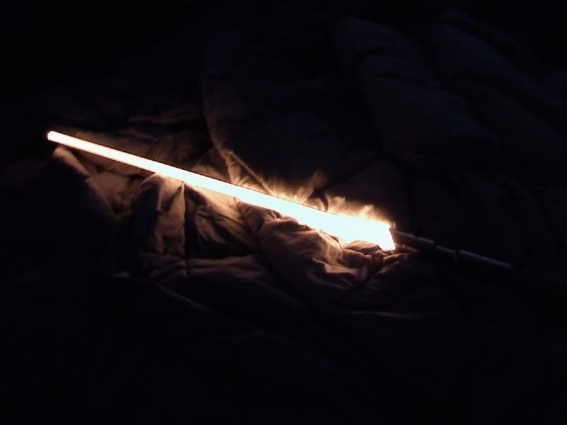
    Here it is with the polyp inside. It is obviously MUCH brighter!


    I highly appreciate everyone's help on solving this mystery.

  5. #105
    Jedi Initiate vargose's Avatar
    Join Date
    Jul 2008
    Location
    St. Louis, MO
    Posts
    393

    Default

    No problem. I am glad it worked for you.

  6. #106

    Default

    Looks great! Congrats.
    There's always a bigger fish.

  7. #107
    Sith Warrior Sairon's Avatar
    Join Date
    Sep 2008
    Location
    Calgary, Alberta, Canada!
    Posts
    1,603

    Default

    That looks much better! Glad we could help.
    New to the forum: READ, READ, READ! it's the best way not to get flamed.
    Time for a kirby dance <('-'<) (><) <('-')> (>'-')> (>'-'<)<('-'<) (><) <('-')> (>'-')> (>'-'<)

  8. #108
    Jedi Initiate vargose's Avatar
    Join Date
    Jul 2008
    Location
    St. Louis, MO
    Posts
    393

    Default

    I created a wiring diagram for those who only want a single switch but want full power to their LED. The porblem is the cheap toy hasbro boards don't put out enough current for most LEDs. If you want the 1000ma or even 1400ma it takes to run most LEDs you need a separate circuit with a separate switch. I used a relay for the second switch which is powered by the board. See attached diagram. Be careful to check how much voltage your hasbro board will take. Some are ok with 6v, but some people use 5v regulators to be safe.

    hasbroRelay.jpg
    Last edited by vargose; 03-30-2009 at 10:09 AM.

  9. #109

    Default

    Quote Originally Posted by vargose View Post
    I created a wiring diagram for those who only want a single switch but want full power to their LED. The porblem is the cheap toy hasbro boards don't put out enough current for most LEDs. If you want the 1000ma or even 1400ma it takes to run most LEDs you need a separate circuit with a separate switch. I used a relay for the second switch which is powered by the board. See attached diagram. Be careful to check how much voltage your hasbro board will take. Some are ok with 6v, but some people use 5v regulators to be safe.

    hasbroRelay.jpg
    That looks great. Thanks, vargose. A couple of questions. Since a Hasbro board takes a momentary switch, and a Buckpuck requires a latching switch, I'm assuming you need a specific kind of relay for this set-up. What kind is required? Also, your digram shows two yellow wires from the relay joined together and then joining the positive lead from the battery pack. Could you explain that? Thanks in advance!
    There's always a bigger fish.

  10. #110

Bookmarks

Posting Permissions

  • You may not post new threads
  • You may not post replies
  • You may not post attachments
  • You may not edit your posts
  •