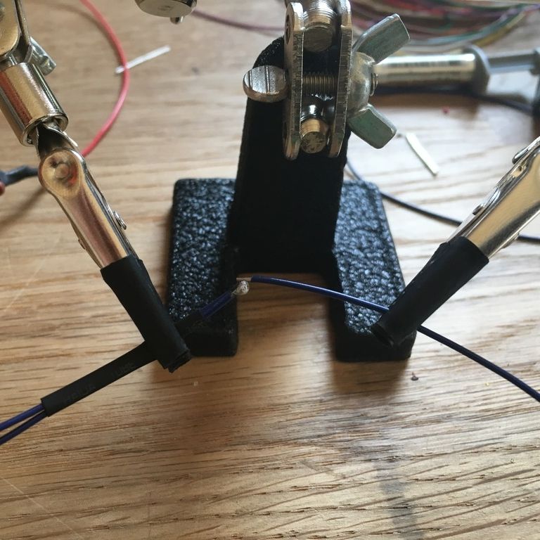
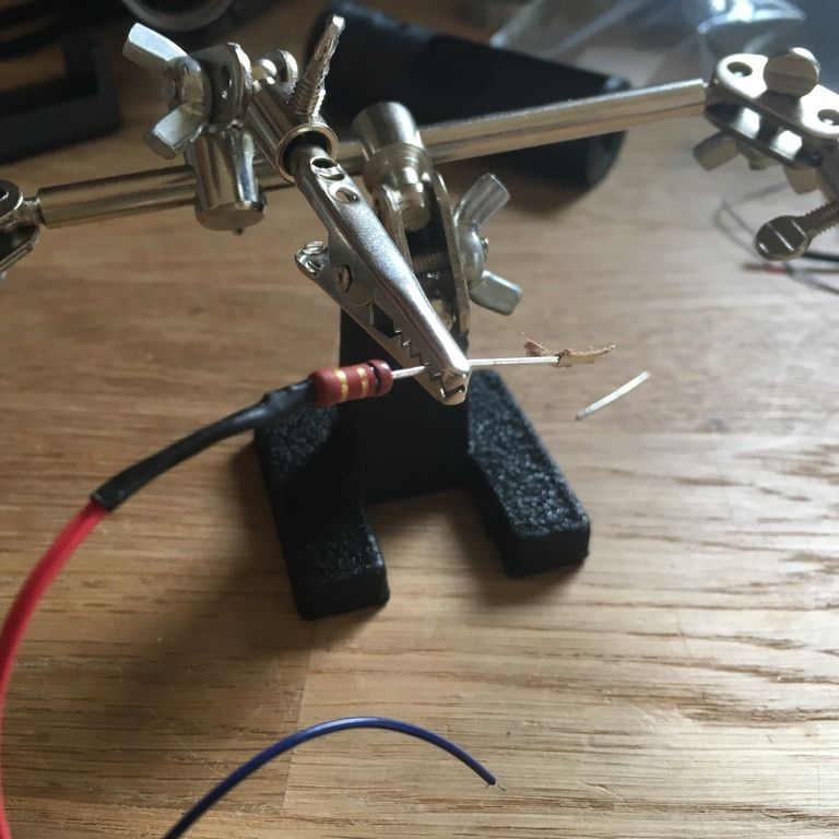
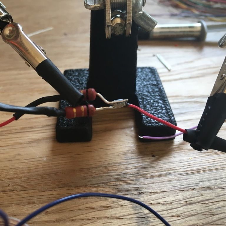
Positive wires from blue emitters join and connect to 1 Ohm resister
Positive wire from white emitter joins the positives from blue
Negative wires from blue emitters join into one wire


Positive wires from blue emitters join and connect to 1 Ohm resister
Positive wire from white emitter joins the positives from blue
Negative wires from blue emitters join into one wire
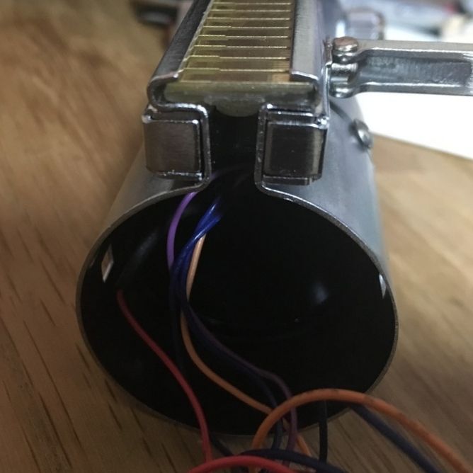
Speaker wiring
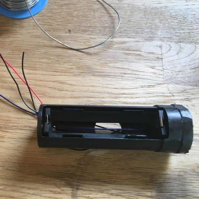
Battery holder wiring
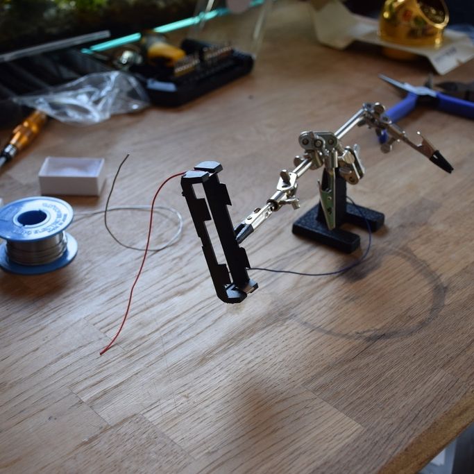
Speaker holder assembly
I had to shave down the "lip" of Speaker Holder V6 quite a lot in order to fit it inside the bottom tube of Graflex 2.0 kit.
It needs to be small enough so that it won't spin with the bottom tube when all the wires are soldered.
Last edited by OLDY; 06-01-2017 at 07:27 PM.
Switch wiring under the red button
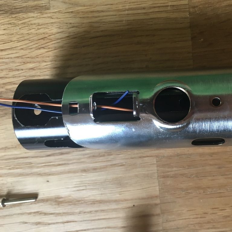
2 switch wires have to go though 1" blade holder before soldering the switch itself.
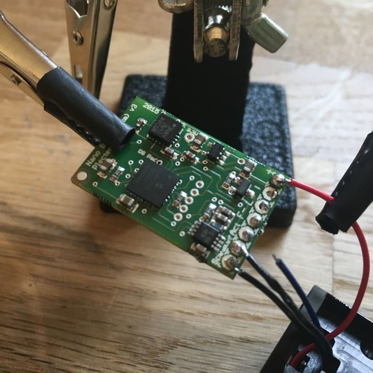
Nano Biscotti v3 wiring
Speaker wires then, positive and negative from the battery holder.
A negative and a ACT for the switch.
Last edited by OLDY; 06-01-2017 at 07:55 PM.

Looks like a bridge there between negative main and ACT pcb's. I think one wire of the switch on NB3 goes to negative, but should not be bridged to ACT PCB.
Last edited by Tom Tilmon; 06-01-2017 at 08:01 PM.
"Mistakes are our greatest teacher."
Thanks Tom.Originally Posted by Tom Tilmon

Yeah, it looks like they are.
I now have completed this build and the saber is working but I will check that connection.

I appreciate your extensive photo documentation.
Completed speaker module
I wrapped the main board with tape in order to secure it onto the speaker holder.
Speaker holder needs to be shaven down to look like this for it fit the bottom tube of the bottom tube from the top.
Bottom section assembly
Speaker module sits nicely above the 6 grip screws.
Clamp card
the circuit card is too thin to stay in the slot so I sanded the babble card and pushed both of them into the slot.
I didn't really need to sacrifice the bubble card for this purpose. I could have used any piece of plastic.
Last edited by OLDY; 06-04-2017 at 07:42 PM.
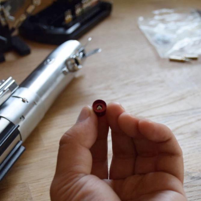
Red button switch
I glued a small screw (not part of the kit) inside the red button to give it enough height to actually push down the switch.
Then I glued the red button to the switch with tiny amount of super glue.
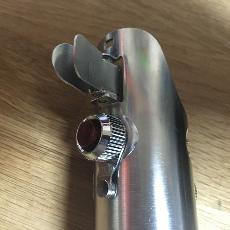
Final assembly

Last edited by OLDY; 06-04-2017 at 07:44 PM.
Thanks Jenny.
Glad to to be a help.
On the previous page, it appears (to me at least) there may also be a solder bridge on the led module... between the red & purple wires.
Or maybe it's just an illusion caused by the angle of the photo, I can't be too sure. You might want to check though if you haven't tried
powering it up yet... better safe than sorry.
 Posting Permissions

 Reply With Quote
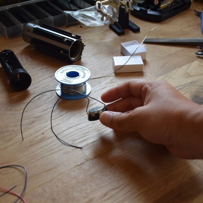

Bookmarks