Page 1 of 4 1 2 3 ... LastLast
Results 1 to 10 of 36

Thread: Blowing momentary switches

  1. #1

    Default Blowing momentary switches

    So, I keep on blowing the LED's in my momentary switches. I got it to work one time, but I tried different wiring according to a diagram I pulled from Amazon, and then went back to the original way I was doing it (based on another diagram from Amazon), and now it isn't working either. The diagrams are below

    image.jpg

    image.jpg

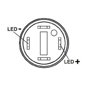
    However, these diagrams don't really show what the terminals are themselves. The bottom one is grounds but ground for the switch, or the LED?

    What I have in mind is to have two illuminated switches, one that will come on/off via recharge port and kill key, and the other wired directly from the power source (18650, 3.7) that will turn on and off whenever I press the button. I am using a NB v3, and DynaOhm resistors. I've only done alligator clips/no soldering to test the connections.

    Both diagrams looked like they would apply to what I want to do, but I'm not sure now.

  2. #2

    Default

    If you have switches from the TCSS store, the LED terminals are labeled in this diagram:


    The unlabeled terminals are for the switch mechanism itself.

    If the LED in the switch is blowing, then your resistor isn't being wired correctly. The DynaOhm needs to go on the positive side of the LED.
    We all have to start somewhere. The journey is all the more impressive by our humble beginnings.

    http://led.linear1.org/1led.wiz for the lazy man's resistor calculator!
    http://forums.thecustomsabershop.com...e-to-Ohm-s-Law for getting resistor values the right way!

  3. #3

    Default

    Quote Originally Posted by Silver Serpent View Post
    If you have switches from the TCSS store, the LED terminals are labeled in this diagram:


    The unlabeled terminals are for the switch mechanism itself.

    If the LED in the switch is blowing, then your resistor isn't being wired correctly. The DynaOhm needs to go on the positive side of the LED.
    Thank you! I will try things out again tonight.

  4. #4

    Default

    Actually, looking again at the switches I have (from the saber shop) positive and negative are switched.

    image.jpg

  5. #5

    Default

    Quote Originally Posted by Schwizzle View Post
    Actually, looking again at the switches I have (from the saber shop) positive and negative are switched.

    image.jpg
    Turn the switch 180 degrees and they will match the diagram if the switch is labeled the + and - always indicate the led. there is no polarity to the switch, it is just a line interrupter.

    Are you putting the DynaOhm on the positive line? post your wiring diagram.

    For an on with power you should have:
    1. a positive feed from the NB + --> the DynaOhm -->Switch LED +
    2. a ground feed from the NB - --> Switch LED-
    3. a line from NB ACT --> switch terminal
    4. a line from Bat- --> Switch terminal
    Last edited by FenixFire; 08-19-2016 at 09:20 AM.

  6. #6

    Default

    Quote Originally Posted by FenixFire View Post
    Turn the switch 180 degrees and they will match the diagram if the switch is labeled the + and - always indicate the led. there is no polarity to the switch, it is just a line interrupter.
    Ok, so the position of the LED color indicator (the dot) doesn't always match the polarity of the LED terminals? I have a larger switch that has the dot in the same place as shown in Serpent's diagram.

  7. #7

    Default

    Quote Originally Posted by FenixFire View Post
    Turn the switch 180 degrees and they will match the diagram if the switch is labeled the + and - always indicate the led. there is no polarity to the switch, it is just a line interrupter.

    Are you putting the DynaOhm on the positive line? post your wiring diagram.

    For an on with power you should have:
    1. a positive feed from the NB + --> the DynaOhm -->Switch LED +
    2. a ground feed from the NB - --> Switch LED-
    3. a line from NB ACT --> switch terminal
    4. a line from Bat- --> Switch terminal
    Yes, well, for what I thought was the positive terminal I've been putting the dynaohm on each time, but I think I've been paying too much attention to the position of that color indicator.

    So, to just test the LED, all I should have to do is put the resistor on the + LED terminal, then attach my positive lead from the battery, then connect - lead from battery to the - LED terminal, and the LED should light up correct?

    I will do some wiring diagrams later after kids are in bed, and if I'm not dead asleep by that point

    Thank you all for the replies btw.

  8. #8

    Default

    Here's one way to save a little cram-fu trouble by reducing your wires from 4 to 3...

    diag 1.jpg
    So certain are you; always with you it cannot be done.
    Hear you nothing that I say?


    http://www.plecterlabs.com/Media/Doc...deTutorial.pdf
    http://forums.thecustomsabershop.com...Hardware-Saber
    ---------------------

  9. #9

    Default

    So, along with getting the terminals straight, I've also come to realize that my dynaohm was bad too. I had a second one and tried it and the LED's were lighting right up. However, the 2nd dynaohm went bad too. I'm not completely sure why, except I may have inadvertently moved the positive alligator clip (they're tricky on those small terminals) and it touched one of the switch terminals for a brief moment. I thought that it shouldn't matter though since the switch terminals don't have polarity?

  10. #10
    Jedi Padawan
    Sith Adept
    Jedi Padawan
    Cire Yeldarb's Avatar
    Join Date
    May 2013
    Location
    United States
    Posts
    595

    Default

    The Dyna-ohm has an "in" side and an "out" side, are you making sure to put it facing the right way in your circuit?

Bookmarks

Posting Permissions

  • You may not post new threads
  • You may not post replies
  • You may not post attachments
  • You may not edit your posts
  •