Page 1 of 2 1 2 LastLast
Results 1 to 10 of 11

Thread: Etching design on tapered pieces

  1. #1

    Default Etching design on tapered pieces

    Hello all!

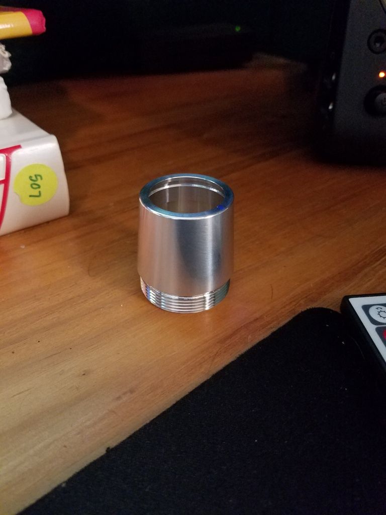
    I've run into a bit of a snag in designing etches for my saber. Specifically, this piece;


    This is MPS Pommel Style 8. It has a taper from the threaded end to the open end. This is difficult to explain, but I'll do my best. I need to create an etch template that is the exact surface area of the piece before I can design the actual etch. I believe the shape is called a "truncated cylinder." Has anyone had any experience with etching this or another tapered piece? Any info/advice you can offer would be much appreciated

  2. #2

    Default

    The low tech way to do it is to wrap a piece of paper around it and trace the contour of the edges.

  3. #3

    Default

    Quote Originally Posted by jbkuma View Post
    The low tech way to do it is to wrap a piece of paper around it and trace the contour of the edges.
    Low tech-unless you have the cad that you can pull and flatten the surface, for export as a pdf drawing, it is the only way.

    Well unless you want to do it mathematically by measuring the upper and lower diameters and calculating the circumference of each edge. Yeah well it is a complicated process full of equations I have not used since I switched from engineering to design almost 20 yrs ago. Ill see if I can find you a quick walk through or tutorial. By the way the term you are looking for is "Truncated Cone".
    Last edited by FenixFire; 07-12-2016 at 02:23 PM.

  4. #4

    Default

    http://www.vitutor.com/geometry/soli...ated_cone.html

    Tells you how to calculate it but not how to physically draw it.

  5. #5

  6. #6

    Default

    Forget that Wrap a piece of paper round it, like jb said.

  7. #7

    Default

    yep, hoped that's what he would do...but if he was wanting to build the stencile in Illustrator or another vector software he would need to know how to translate that into the software.

  8. #8

    Default

    Should be easy enough to scan and trace in illustrator than scale it with vertical dimension.

  9. #9

    Default

    Quote Originally Posted by jbkuma View Post
    Should be easy enough to scan and trace in illustrator than scale it with vertical dimension.
    Whoa whoa whoa, you lost me. I was hoping to be able to do the design in illustrator, but I'm not following with "scanning and tracing." If at all possible, I want to cut out possibility of human error and create the shape itself digitally.

  10. #10

    Default

    Quote Originally Posted by Firestorm1964 View Post
    Whoa whoa whoa, you lost me. I was hoping to be able to do the design in illustrator, but I'm not following with "scanning and tracing." If at all possible, I want to cut out possibility of human error and create the shape itself digitally.
    It's really not that hard to make it extremely accurate with this method, you should be able to make a very precise representation. You can very easily print and test fit it to make sure before you go into design. Your measurements can very easily introduce just as much or more margin. Using any other method, even a 3D laser scan,j has some margin of error. You'll also have a margin based on the medium you transfer your design to. The thickness of the medium can easily tweak your alignment as much as anything else.

    You can scan, trace, print, and test fit in less than 15 minutes if you have any experience in illustrator. Tweaking it, if necessary, should take less time than this discussion.

Bookmarks

Posting Permissions

  • You may not post new threads
  • You may not post replies
  • You may not post attachments
  • You may not edit your posts
  •