


The parts came in from TCSS last week! I was inside most of the day watching the kids while my wife worked on some projects outside, so I took the opportunity to dive in, and after a few hours work, I think I'm just about done. Here are the parts I was working with including the saber body I'd already made. You can see that I added the wiper blade vanes to the lower grip. I put them on with a high strength double sided foam tape, but it's grey and you can see it from the sides, so I'm not sure if I'm going to keep it that way or not. Also, I lucked out and my wife got my son a basic soldering kit for Christmas, so I had access to a soldering iron and solder.
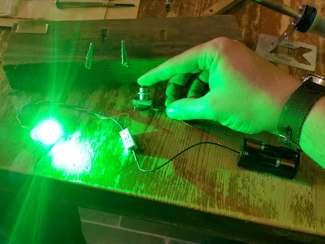
I tried my hand at soldering after looking online at a few youtube videos, and I just couldn't get the hang of it. I'm usually a fairly quick study, but this kicked my butt. I could get the solder to stick to EVERYTHING except the wire I wanted it to. Eventually I gave up and went to Lowes to see if I could get one of those helping hands for soldering, but they didn't have one. Neither did Michael's (hobby store). They did, however, have alligator clamps for making hair clips or something so I bought some of those, and used them to improvise a helping hand with a 2x4 and a couple nails. The photo below is me testing the diode - I didn't solder it in that position.
Once I got the clips, soldering improved a little. It turned out that no matter how long I let the iron sit, the tip never got hot enough to make the solder flow. I ended up having to use the shoulder of the iron for making all my joints, which wasn't the easiest, but I successfully tinned wires and made all my connections. I used the basic understanding of the TCSS "Building a Basic Saber" video, but with the parts and pieces I'd assembled.
My next moment of confusion happened after I completed making all my connections, and I put batteries in the battery pack. As soon as I put in the last battery, the LED lit up. I assumed I'd left the switch on, until I realized it was a momentary switch. I pressed the switch, and the LED turned off. I let go, and it turned on again. Then I remembered that it was labeled as an emergency test switch. It's function is to CUT power to a circuit when engaged so that emergency triggers due to cut power can be tested. Oops.
I didn't want to buy a new switch, so I cracked it open to see if I could reverse it. Surprisingly, turns out I could. Here's what it looks like inside.
The switch depresses the metal bar seen on the top half of the switch. By default, that bar is tucked UNDER the two metal tabs seen on the bottom half of the switch. When the button is pushed, the bar depresses, and loses contact with the two tabs. I freed the halves, bent the two tabs down some, and reinstalled the top half with the bar ABOVE the tabs. Now when you pres down, it completes the circuit instead of breaking it. Boom. Done.
So here's the completed wiring. Considering how much effort and learning went into it, it's remarkably simple looking.
Let there be LIGHT!!!
So then I assembled it all. The LED aluminum shell is designed to work with the MHS parts, so I had to sand the lip down some to fit inside the drain assembly. The say it's made, once it was in it was too loose, so I used a couple layers of cork sheeting I had around to snug it up in the hilt. The battery compartment was a good fit with the addition of a layer of foam to snug it in place. My TCSS blade was a little loose in it's mount, so I bought a small length of black polyethelene drain pipe and sanded it down to form kind of a gasket in the throat of the emitter. I put it all together and presented it to my son. I think he likes it.
And since I forgot to take a photo of it completed, here's a quick video I took:
For a final touch, I went out to Lowes and the garage and rummaged around for parts to make a blade plug. It's just some brass parts superglued together, but it looks good for now. I'm sure it will break at some point soon.
So that's my first build. I know this thread hasn't gotten too much discussion, but I'd love to hear your opinions of this saber. It was a fun adventure to make.


 Reply With Quote


Bookmarks