Page 1 of 2 1 2 LastLast
Results 1 to 10 of 17

Thread: Wiring check, please.

  1. #1

    Default Wiring check, please.

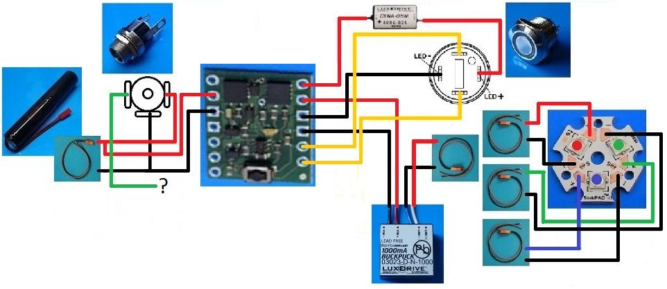
    I ordered all but one part for a stunt saber that I'll be making for my little brother. I have two diagrams. One with resistors and one with a 4 wire 1000 mA buck puck. I'd like both diagrams checked just in case I don't get my hands on a buck puck. I looked all over the forum and these are what I came up with, as far as wiring the momentary to latching converter as well as wiring the recharge port without a soundboard.
    Any feedback and criticism is appreciated.

    7.4 1400 mAh 18500
    DynaOhm for 16mm Anti Vandal Short Momentary Green Ring Switch
    4 wire 1000 mA buck puck
    Tri-Cree R/G/rB LED

    First, resistors.


    Second, 1000 mA buck puck.
    Last edited by daaguilar; 01-28-2016 at 11:45 PM.

  2. #2

    Default

    Wow, ok I'm pretty sure that the diagram I used for the converter is old. If not old its definitely a different one. Does anyone know where I can find a diagram of the converter currently sold in the store? I think it's basically the same just with different switch posts.

  3. #3

    Default

    Ok so after comparing the one sold in the store and the diagram I used, I'm assuming that this is how I need to wire it up. The one question I have (if all is correct) is where do I wire the " board -" post from the recharge port?


  4. #4

    Default

    The recharge port is wired wrong. The middle leg (the black wire) that you have connected to the converter board and the battery should only connect to the battery. The left leg (green wire) should be connected to the converter board.

  5. #5

    Default

    So battery positive runs to the recharge port as well as the converter board and the battery negative runs only to the recharge port?
    Does my positive run to the correct pad on the board? And where is the left leg (green wire) supposed to contact the board? And last question, are all of the wires on the right side of the board correct?
    Thank you for your input so far, Generic, I really appreciate it.

  6. #6

    Default

    The green wire should connect to the board where you currently have the black wire connected.

    The recharge port acts like a switch.
    When nothing is plugged in, the switch is closed and current flows from the leg connected to the battery to the leg connected to the board.
    When you plug a charger or kill key into the port, the switch is opened and current no longer flows through the leg connected to the board.

    The right side of the board looks correct. It looks like you'll be using one LED at a time. If you connect two LEDs in parallel to the BuckPuck, it will split the current between them so you'll only be driving your LEDs at 500mA instead of 1000mA.

    If you go with resistors instead, you can run two LEDs in parallel at 1000mA each. You could also use a 3.7 volt battery instead of a 7.4 volt battery and have more room in your hilt.
    Last edited by Generic Jedi; 01-28-2016 at 03:49 PM.

  7. #7

    Default

    Would the 18650 3.7v 3400mAh pack be ok? The 2600mAh is out of stock.
    Would I just splice the positive and negative wires anywhere to have two JSTs for the two LEDs or would it be better to solder two different wires to the pads on the board?
    And are these resistors correct for the 3.7v configuration:
    R - 1.2ohm 3watt
    G - 1ohm 2watt
    rB - 1ohm 2watt

    I'm going to put up a new diagram later tonight to actually illustrate the changes.
    Thank you again got the input!
    Last edited by daaguilar; 01-28-2016 at 08:53 PM.

  8. #8

    Default

    The 3400 mAh battery will work fine with resistors. It doesn't have enough voltage for the BuckPuck though.

    If you want to run two LEDs in parallel at the same time, you'll need two JST connectors. You can wire each to the board, or spice the wires of the board into two sets of wires. Either way will work.

    Using a tri-Cree LED with a 3.7 volt battery solution, the 1.2 ohm 3 watt resistor is good for the red.
    Green, Blue and Royal Blue LEDs will be a little brighter with the 0.47 ohm 0.5 watt resistors.

  9. #9

    Default

    Ok so going the resistor route:
    (Hopefully my final diagram)
    3.7v 3400mAh battery
    Recharge port
    Momentary to Latching converter
    16mm AntiVandal momentary Green Ring switch
    DynaOhm Variable resistor
    R/G/rB Cree XP-E2
    (just listing the main parts)

    Resistors:
    R - 1.2ohm 3watt
    G - 0.47ohm 0.5watt
    rB- 0.47ohm 0.5watt

    Hopefully the attachment looks better to you, the quality and size it cut pretty short for me. But photobucket has been down for maintenance since last night.

    image.jpg

  10. #10

    Default

    Well, I don't have the wiring diagram for that momentary converter handy, so I'm not 100% on how it's wired.

    The only thing I've noticed is that you have two JST connectors, but 3 LED dice. I assume you are going to do manual color mixing, with either one or two dice?

    Edit: Looked up the diagram. You appears to have it wired properly.
    Last edited by Silver Serpent; 01-29-2016 at 01:25 PM.
    We all have to start somewhere. The journey is all the more impressive by our humble beginnings.

    http://led.linear1.org/1led.wiz for the lazy man's resistor calculator!
    http://forums.thecustomsabershop.com...e-to-Ohm-s-Law for getting resistor values the right way!

Tags for this Thread

Bookmarks

Posting Permissions

  • You may not post new threads
  • You may not post replies
  • You may not post attachments
  • You may not edit your posts
  •