Results 1 to 7 of 7

Thread: Wiring Check - Claiomh Solais

  1. #1

    Default Wiring Check - Claiomh Solais

    Hello everyone,

    I'm finishing up the design and procurement phase of my first build and wanted to run the wiring by the community before getting starting some pre-assembly while waiting for the new PCs to come into the store.
    It's probably a bit ambitious for a first build, but I don't mind taking my time learning and tinkering until I get it right.

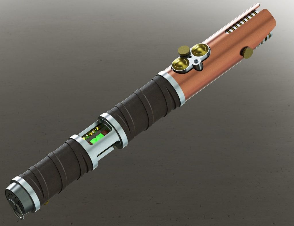
    The Hilt:


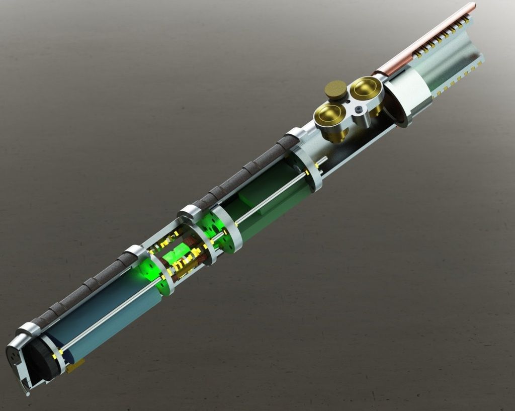
    The Internals:
    From pommel to emitter
    1. Speaker - Premium 28 mm
      *Note: I don't have room to use a speaker holder here, as the Male Extender with Slots has a smaller diameter than the other MHSV1 parts and would not fit over the speaker holder. So my plan is to affix the speaker directly to the threaded rods.
    2. Battery Pack - 7.4V, 1,050 mAh
    3. Crystal chamber with two 5mm RGB Common Cathode type LEDs (With one LED behind each chasis disc)
    4. Anchoring chasis disc
    5. Petit Crouton and Colour Xtender
    6. Switches & Ports
    7. Tri-Cree RGB


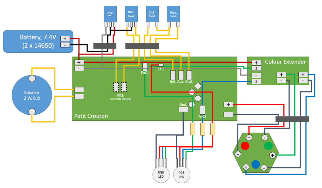
    Electrical Schematic:
    *Note: Black rectangles are multi-wire quick connects. I'll put enough extra wire on them so that I'll be able to pull the chasis out from the top hilt piece.


    I've got some specific questions around the feasibility and wiring of the crystal chamber RGB LEDs.
    1. I'm curious as to how the PMW signals work, are they constant voltage and vary the current to proportionally control the LED drivers (and thus also the brightness of the crystal chamber LEDs)?
    2. Will pulling current from the PMW signals for crystal chamber LEDs affect the blade drivers/LEDs (Brightness, colour balance, etc.)?
    3. Am I OK to drive two RGB LEDs off of the control signals?

      The LEDs I was thinking of using have the following spec's:
      -Forward Voltage:R ~2.4V, G ~3.4V, B ~3.4V
      -Forward Current:20mA
      So for resistors I think I should use the following:
      -Red: 50 Ohm resistor
      -Green: No resistor
      -Blue: No resistor
      With max 9mA per LED will they be dim? Should I look for an LED with a lower forward current?


    Thanks SO much in advance for any help, I'd really appreciate it.

    Cheers,
    Craig

  2. #2

    Default

    The ignition and auxiliary switches are supposed to share the ground pad. In the diagram, you have them sharing the aux pad.

  3. #3

    Default

    Thanks Generic Jedi!

  4. #4

    Default

    Let me explain a bit about PWM (Pulse Width Modulation). This is the concept used to change the brightness of the LEDs (and therefore the colour that is mixed).

    As stated by Ohm's law, the way we can change the current drawn by a circuit is to change the resistance in the circuit. However there is no easy way to "digitally" change the resistance in a circuit. We must physically change something. So how else can we change the brightness of our LEDs? By changing the pulse width. If I pulse the LED on and off very quickly, faster than your eye can pick it up, it will appear half as dim to you. Now if I pulse the LED at the same cycle speed but have it on 75% of the time and off 25% of the time, it will appear 75% as bright. Get the idea?

    The PWM pads that you wire to the CEx and your RGB CC LEDs are either on or off depending on the state of the pulse. They don't carry different amounts of current to tell the CEx what brightness to make the LEDs. Hope you learned something

    My main concern is that with two CC leds, you might be drawing too much current from the PWM signal pads, which I believe are rated at 18mA max (or not enough current and you will have very dim LEDs). You may be able to negate this entirely by using the on-board Power Extenders and one external one, then wiring each colour of your CC LEDs in series.
    Last edited by NanoRex; 02-23-2016 at 06:54 AM.

  5. #5

    Default

    Thanks Nano Rex, that was very informative

  6. #6

    Default

    Very interesting. I always assumed they were digital potentiometers.

  7. #7
    Sith Warrior darth_chasm's Avatar
    Join Date
    May 2015
    Location
    United States
    Posts
    1,756
    Blog Entries
    2

    Default

    Nice design. Looks like it will be a fun build.
    末末末末末末末末末末末末末末末末末末末末末末末末末 末末末末

Bookmarks

Posting Permissions

  • You may not post new threads
  • You may not post replies
  • You may not post attachments
  • You may not edit your posts
  •