


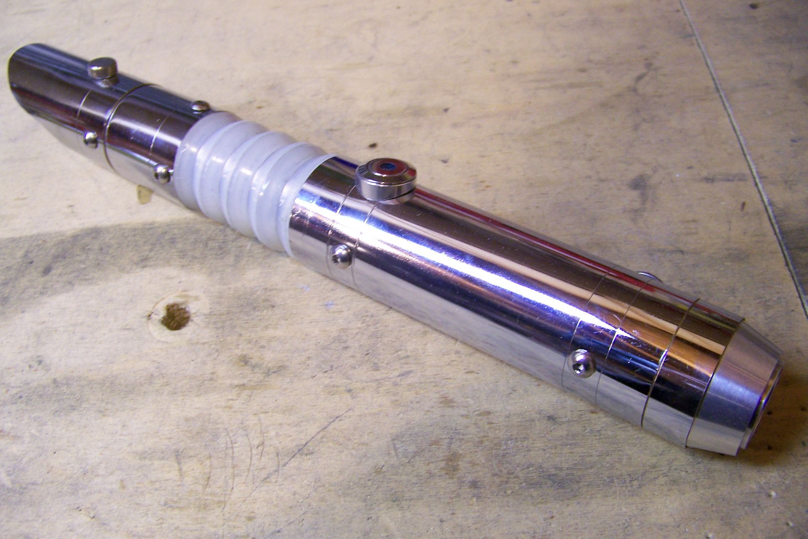
I have an acquaintance in the Rebel Legion Base I'm part of that needs a new lightsaber. He had one that worked well for getting membership, but once we were costuming together at the Grand Rapids Griffins Star Wars Night back in February, and seeing my personal sabers and the ones I recently upgraded for the other members of the club, it became apparent to him that he needed something....different. Since I had finished most of the upgrades for our other members, I offered to see what I could do for him and suggested looking through my site and see if any of the previous builds interested him, and he chose my re-worked Chrome Saber 2 design:
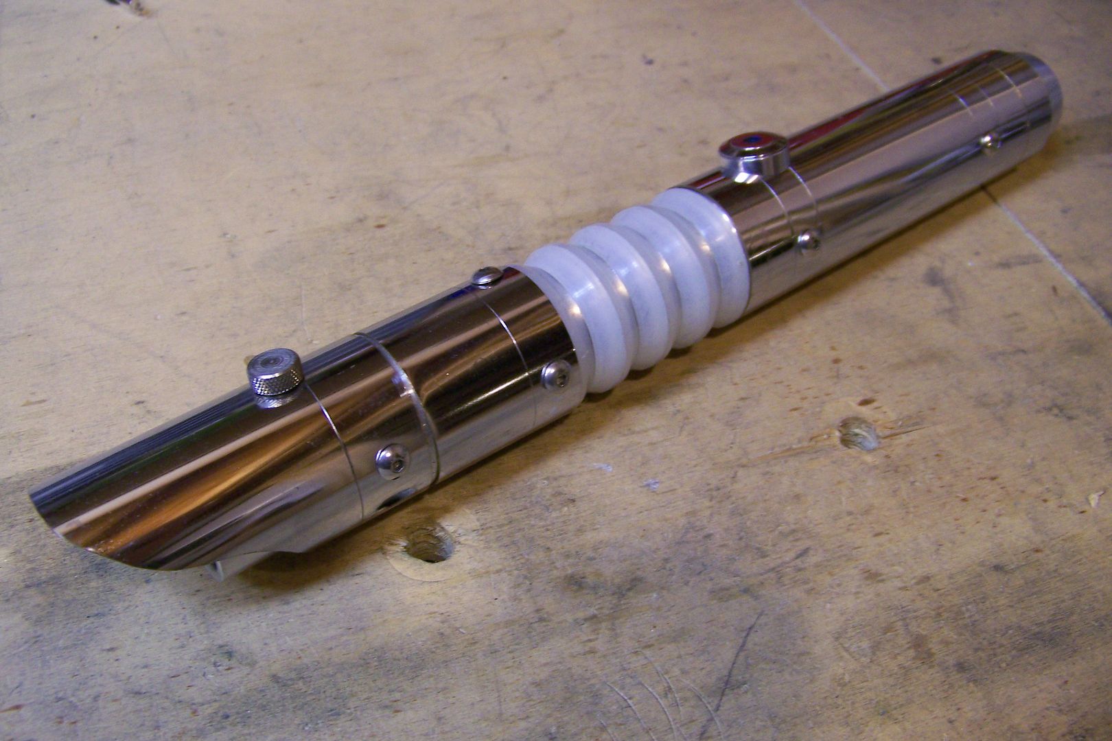
As with that saber, this one will be built on a budget, but hopefully will still look good and most importantly, function as a good trooping saber.
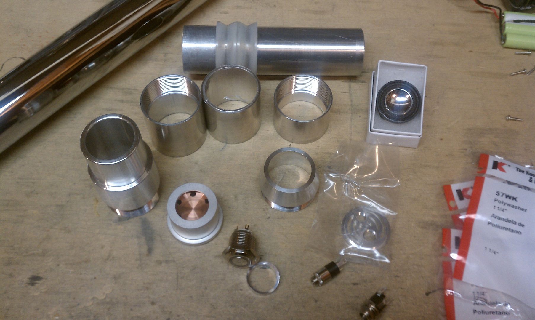
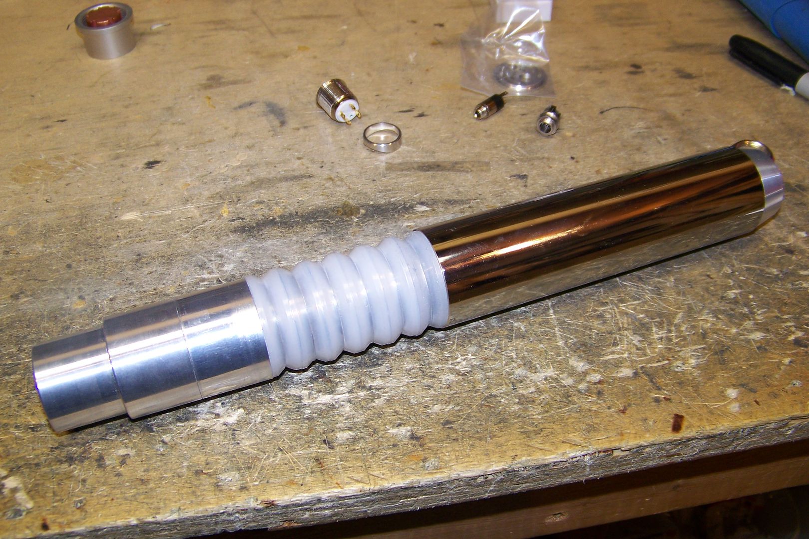
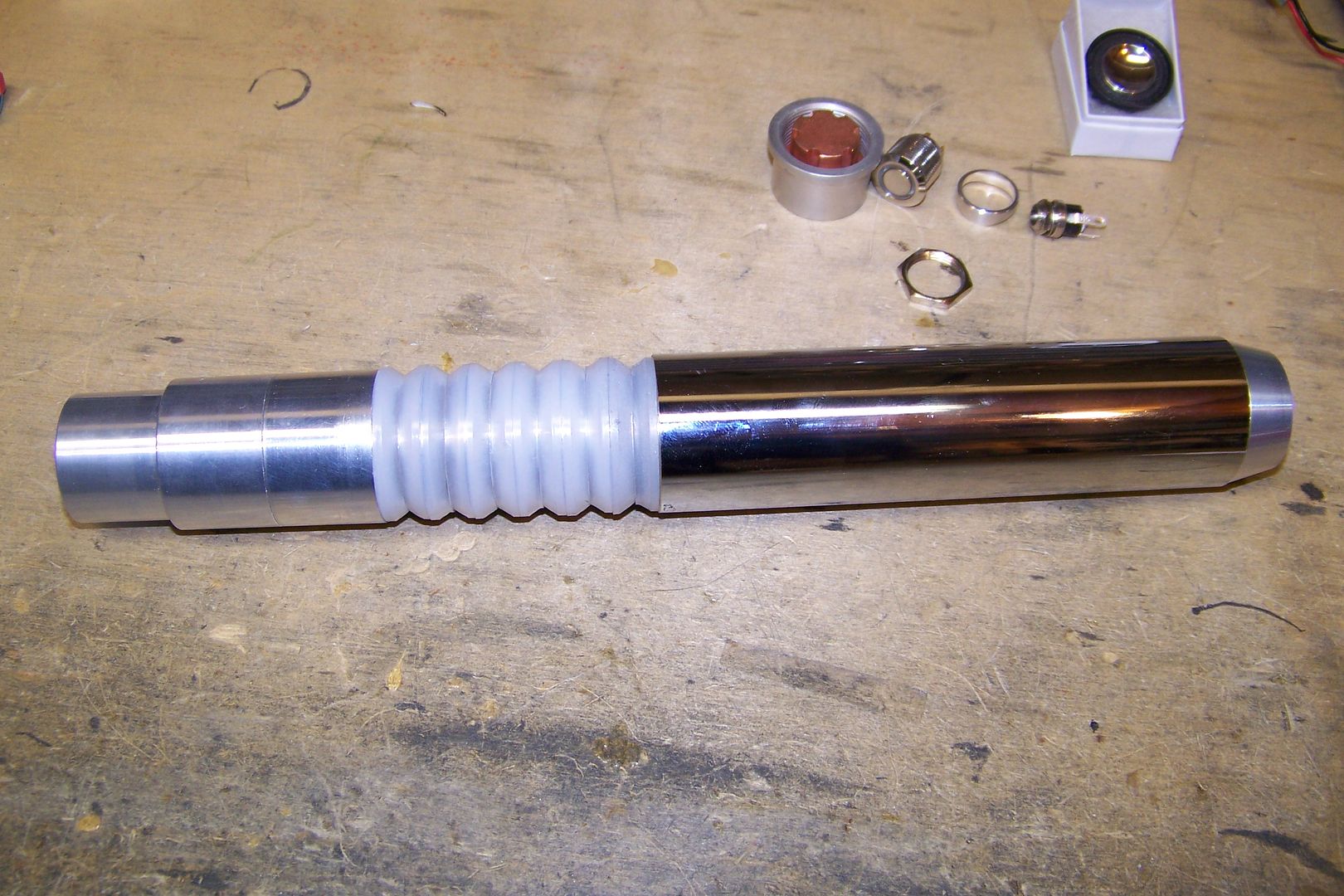
So, here's the basic parts for the hilt:
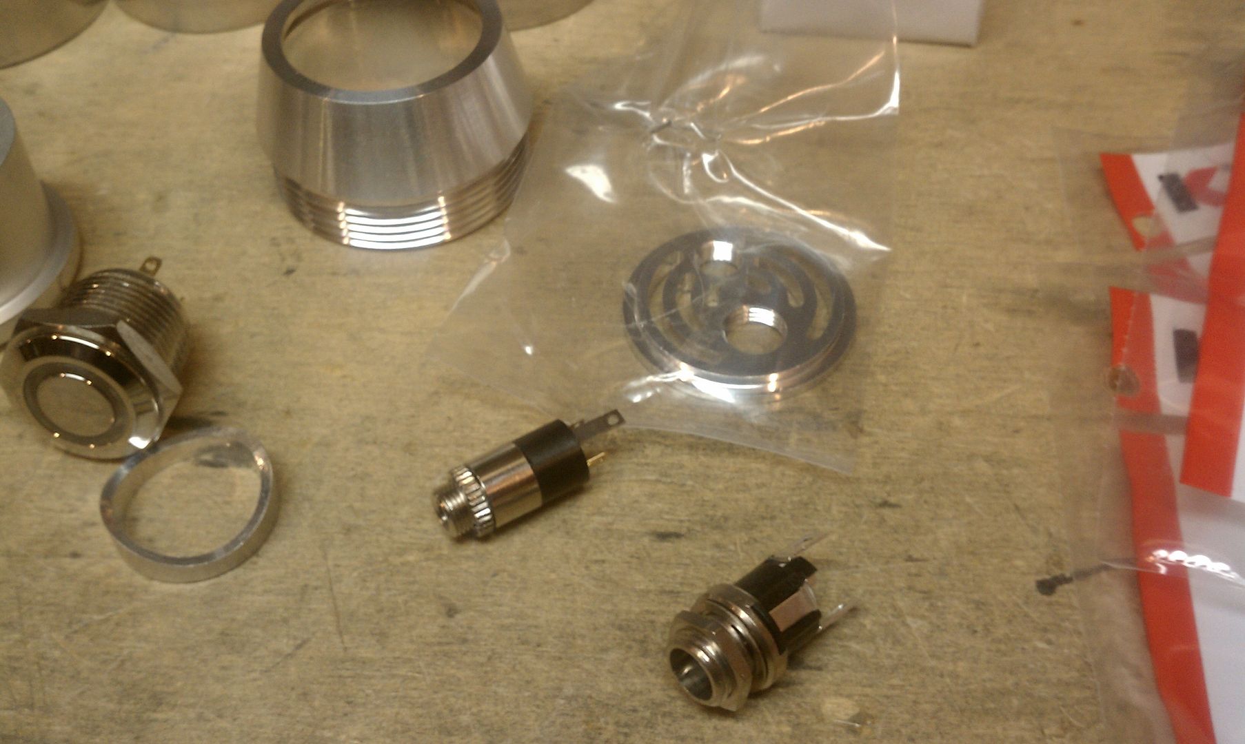
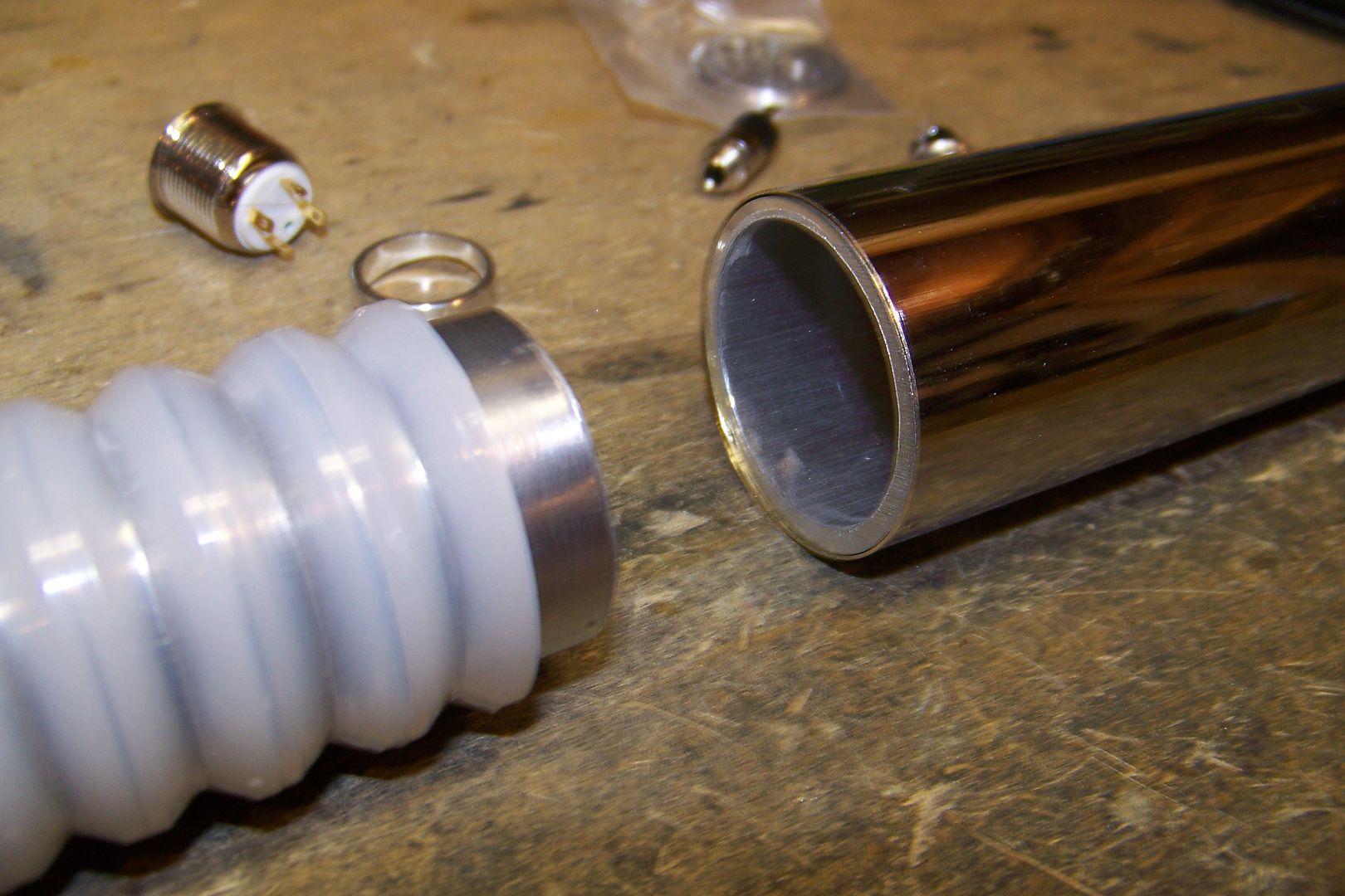
These are the RICE (Real-Time Internal Configuration Editor) and recharge ports....I was thinking about putting these in the pommel, but that will depend on a couple of things that will be worked out between Zark and myself:
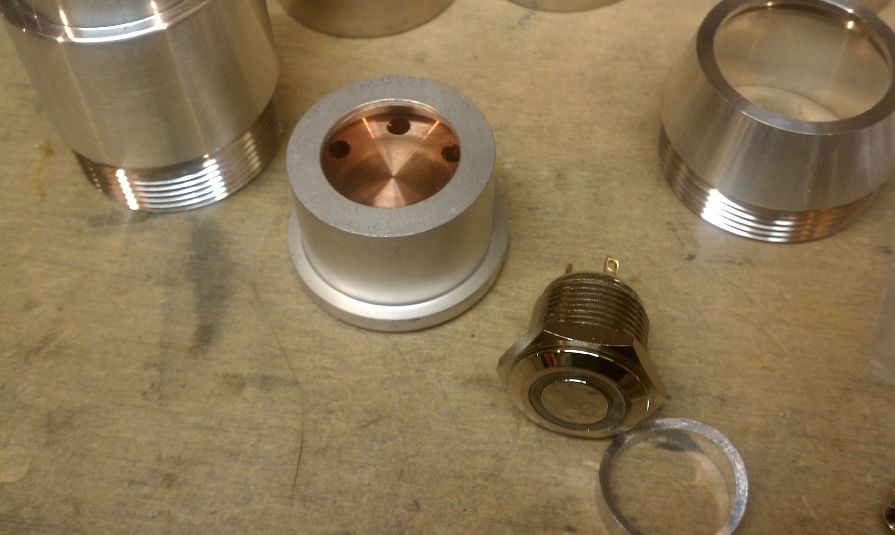
This is the led housing/heatsink assembly:
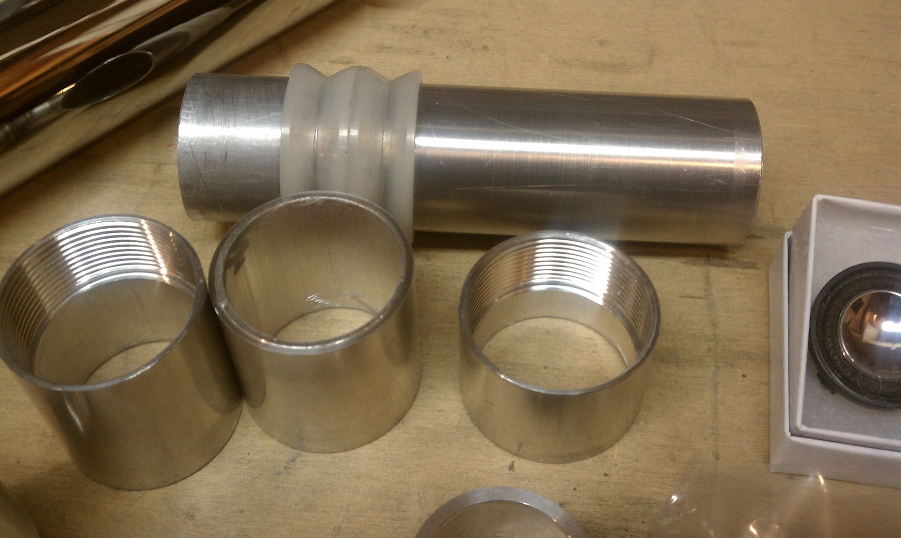
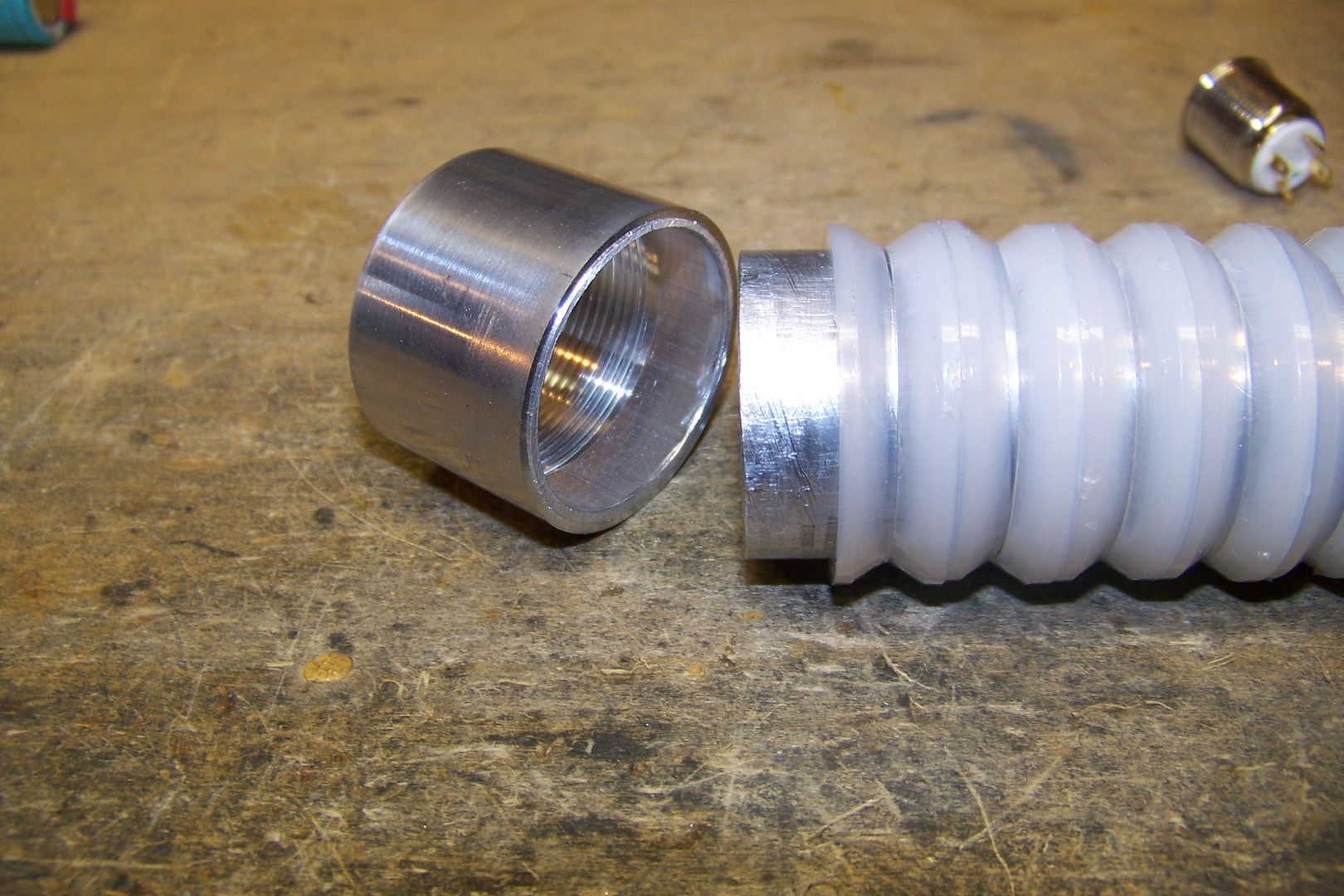
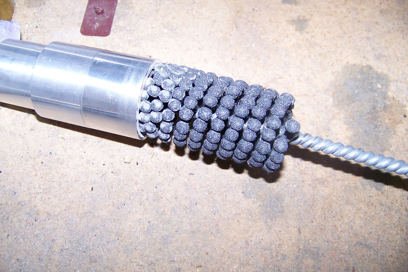
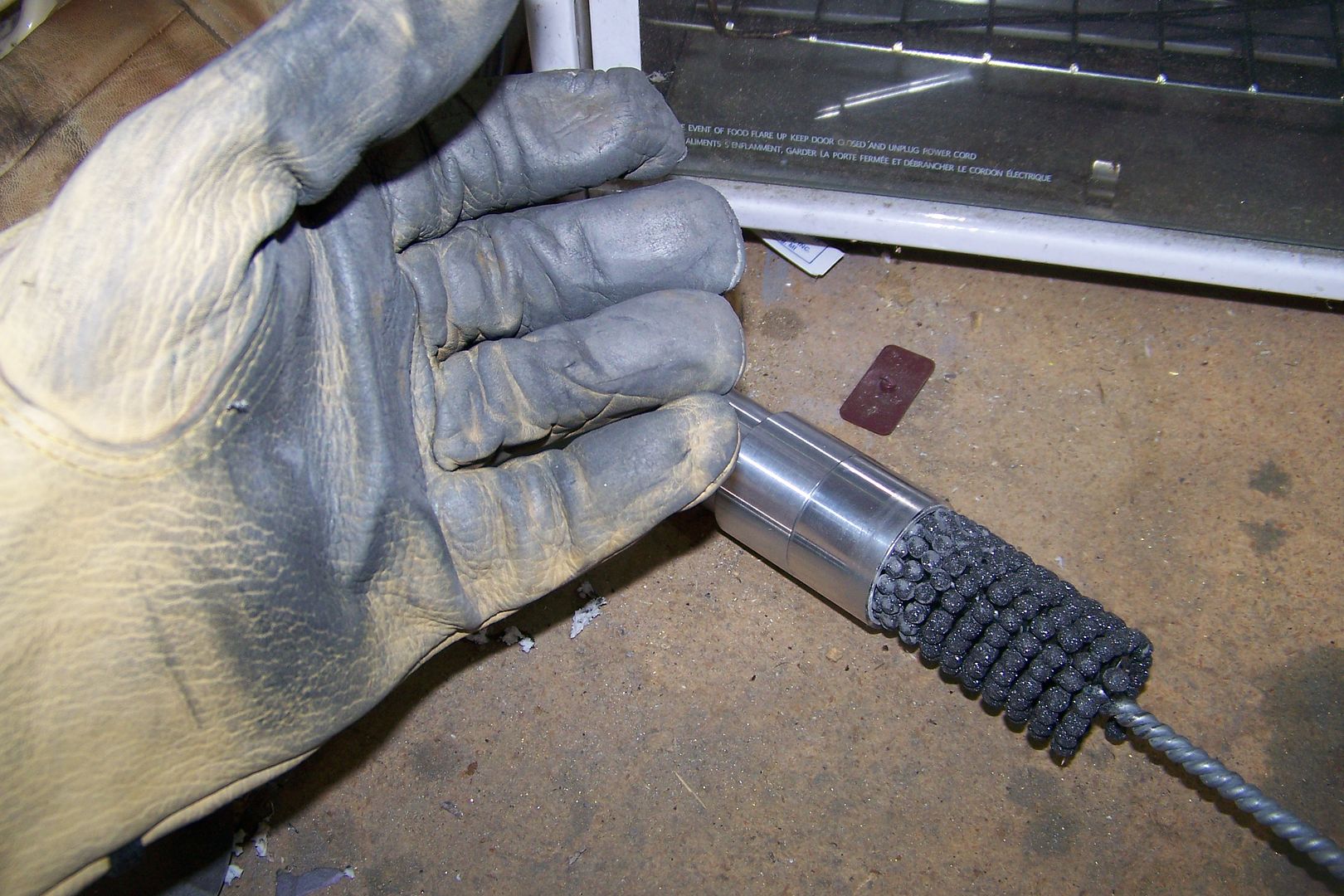
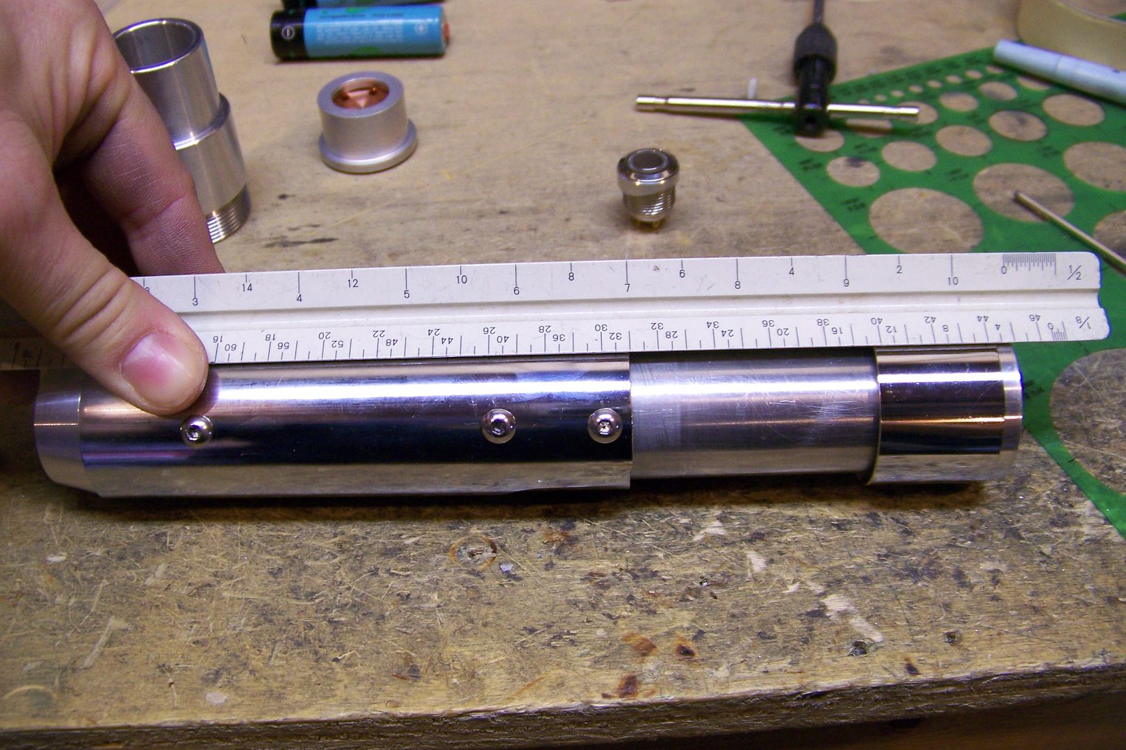
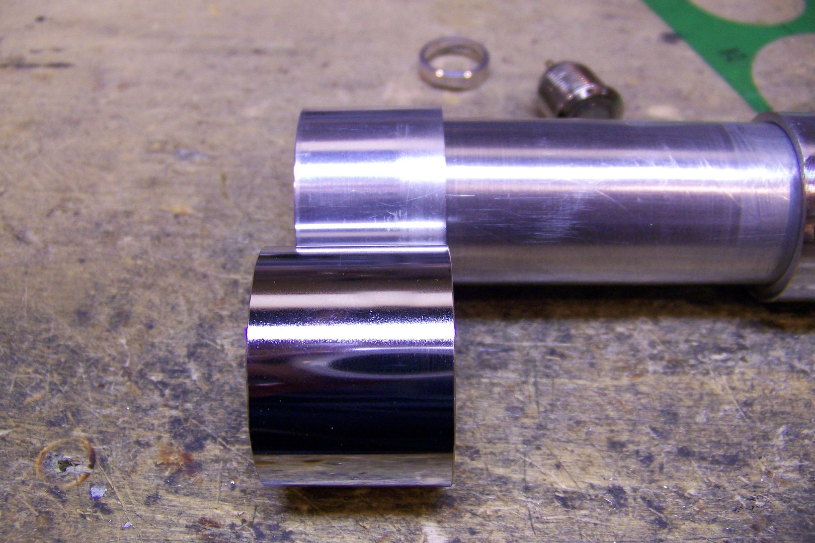
These pieces will make up the front and center sections of the hilt....these started out as a 4" MHS extension that I had Tim at The Custom Saber Shop(TCSS) machine some grooves into to make it easier to part it up into the pieces you see here:
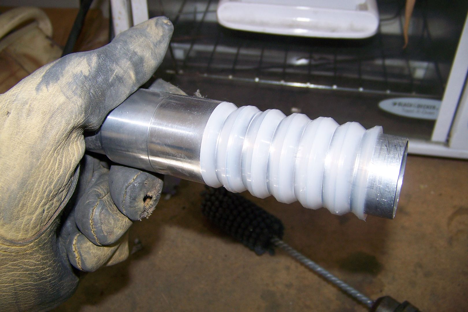
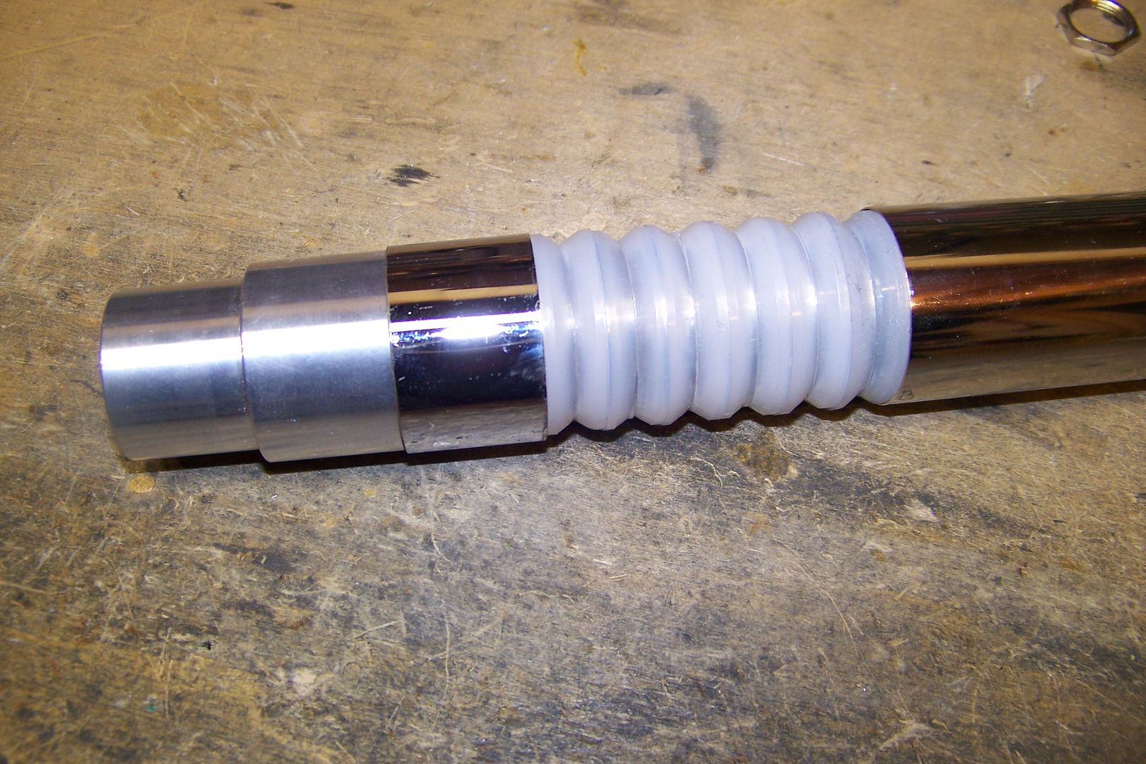
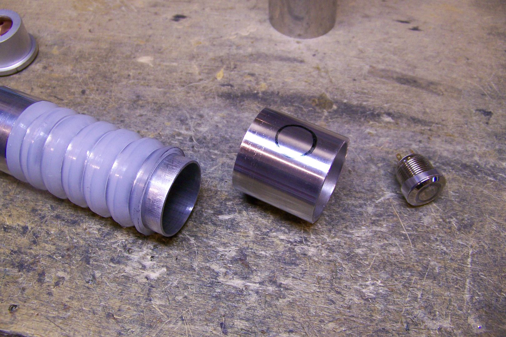
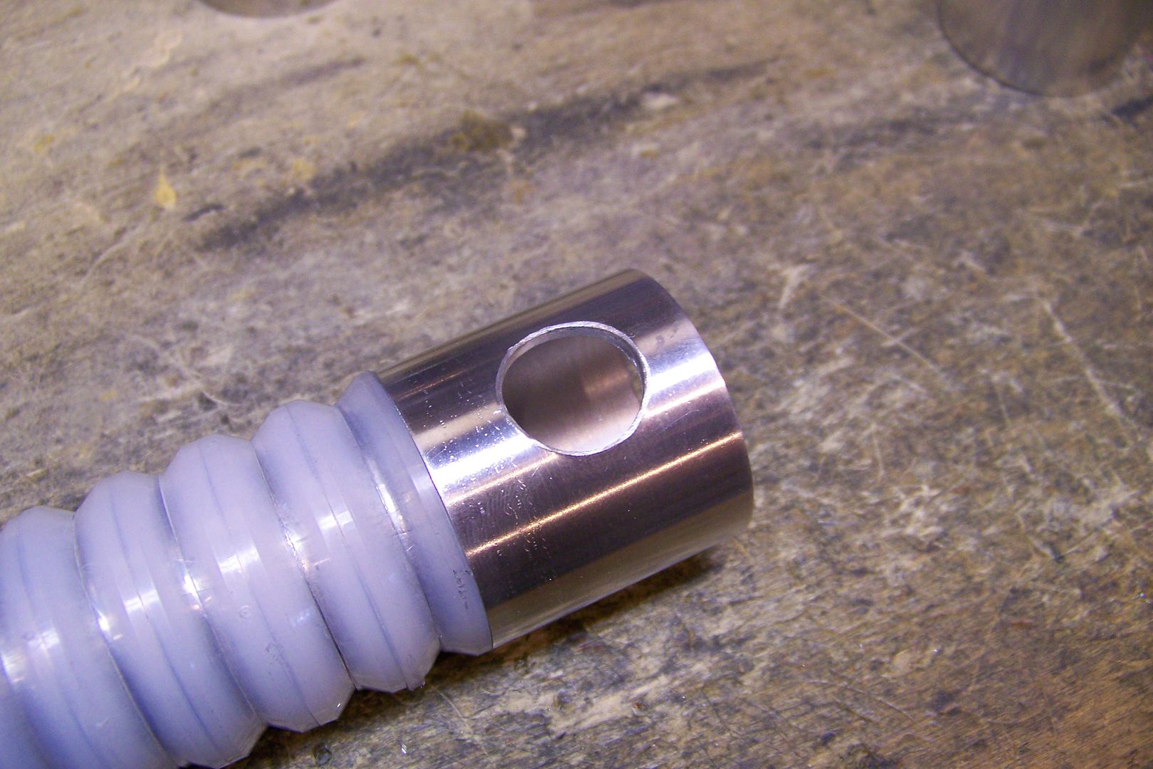
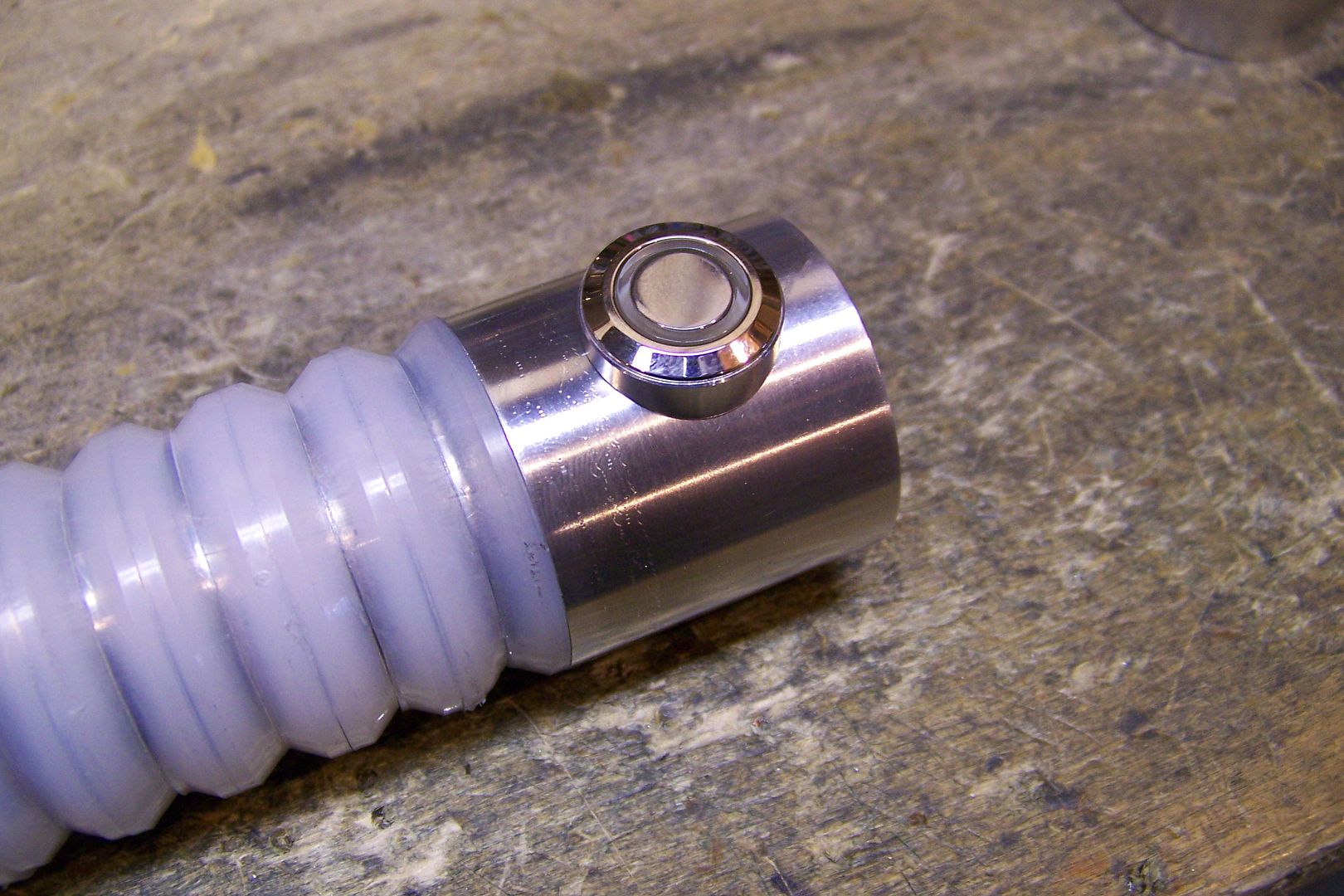
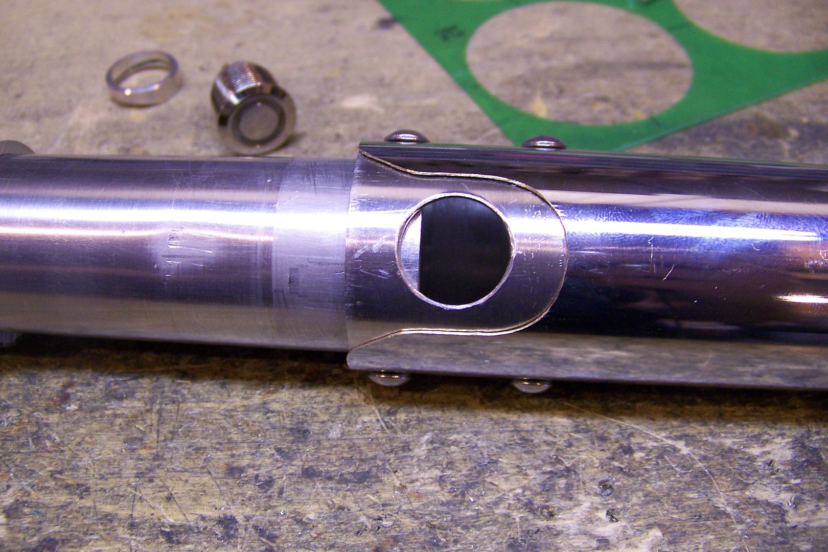
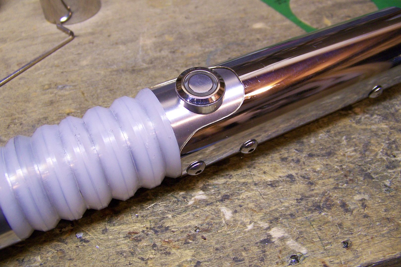
The threaded ends will allow for attaching the blade holder and pommel, the un-threaded center section will house the main switch, and possibly the aux switch as well or the recharge port. The other piece shown there with the polywashers on it will serve as the front grip. The washers are on there as a place holder for now, and may be used on this, but I might have something else in mind for that part, too.
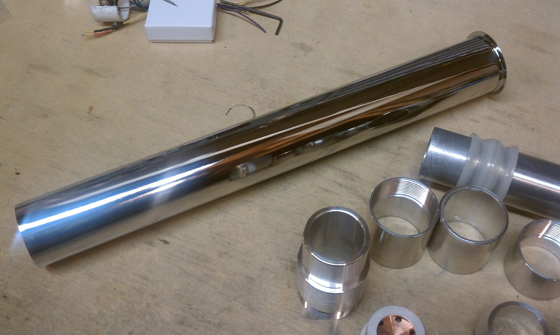
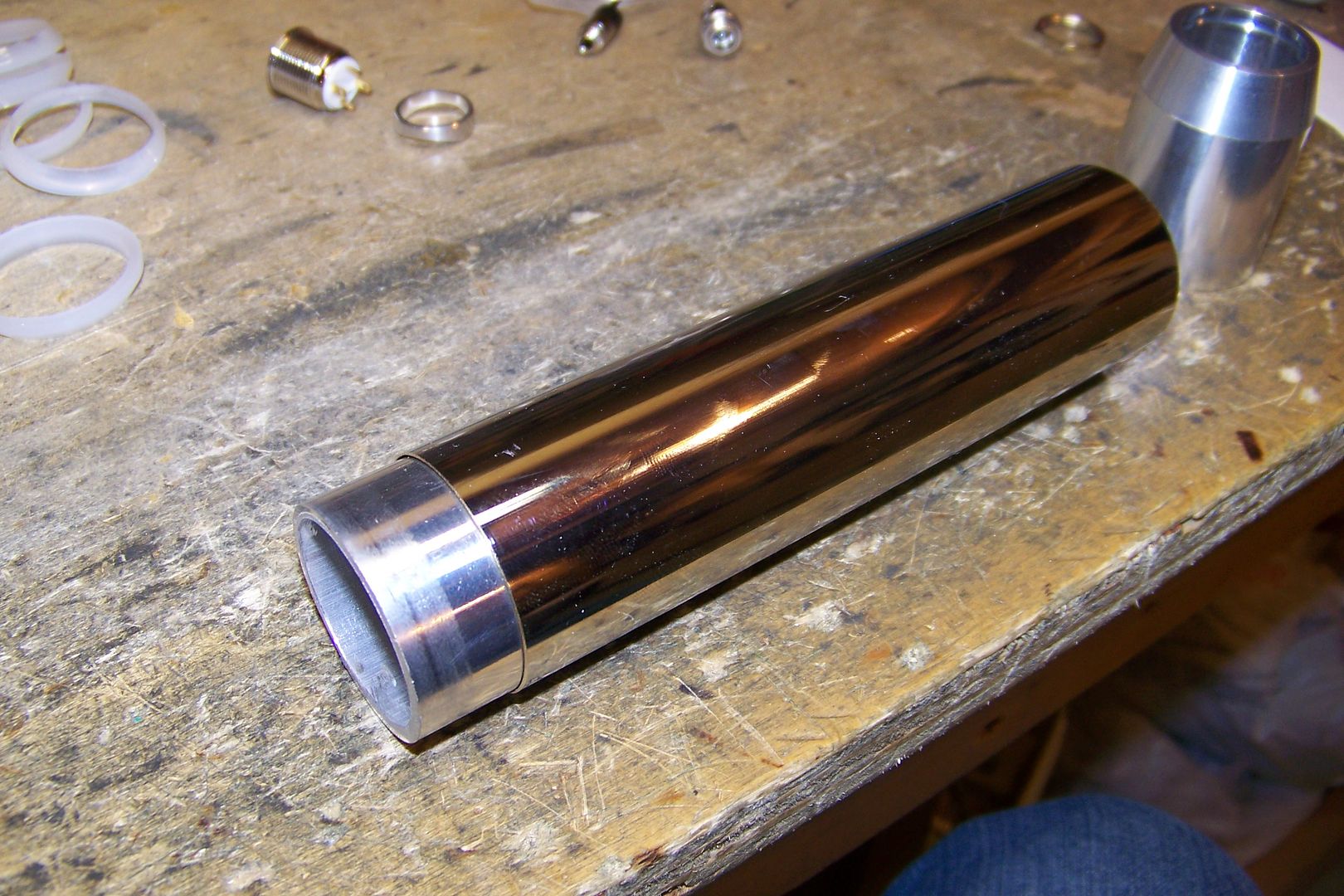
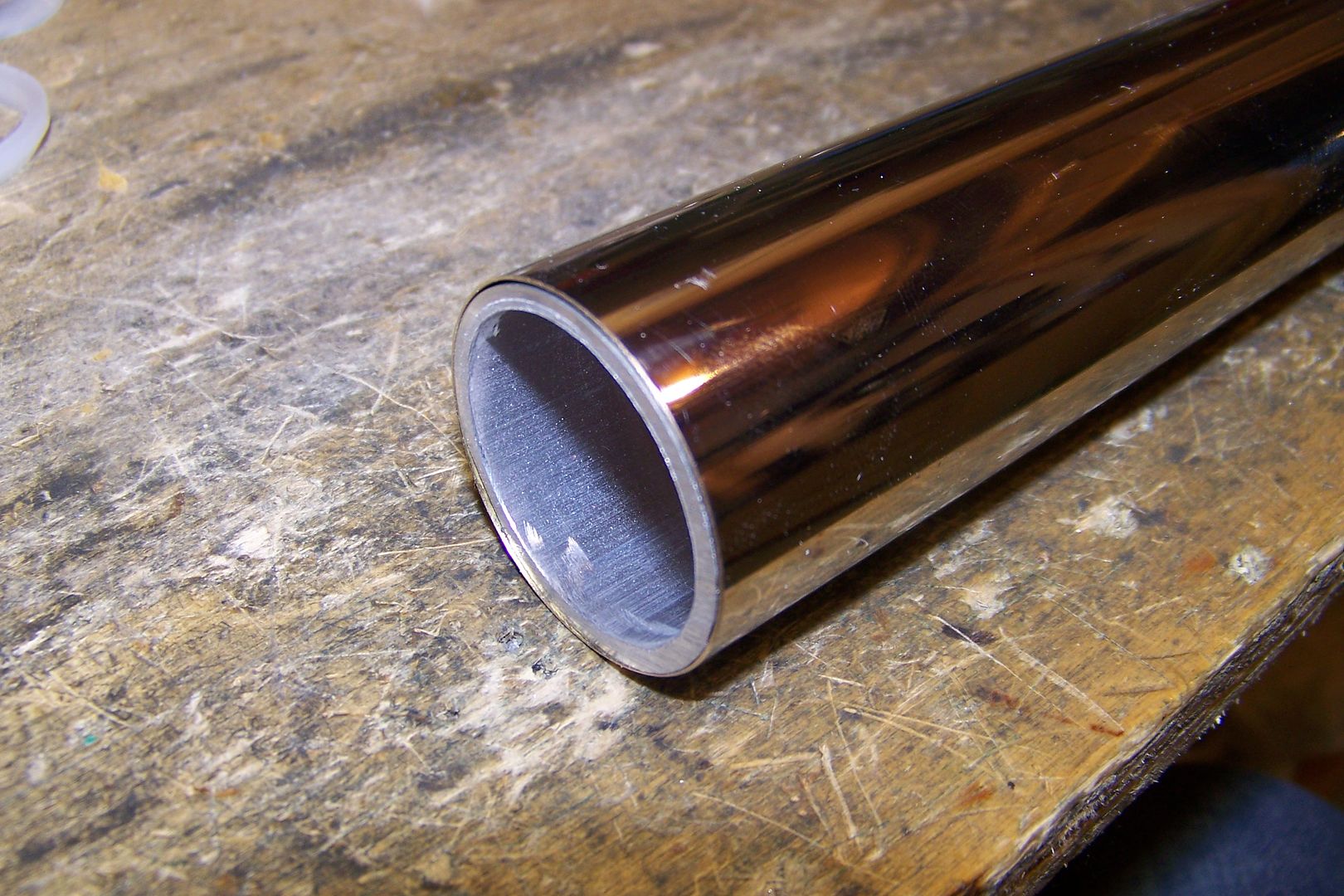
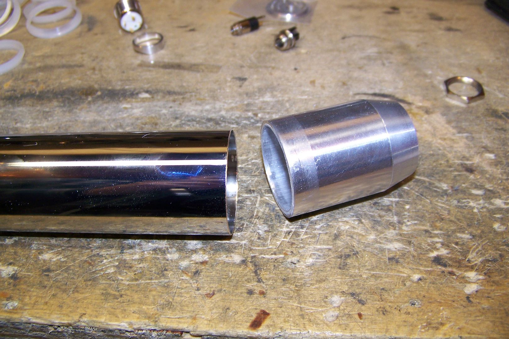
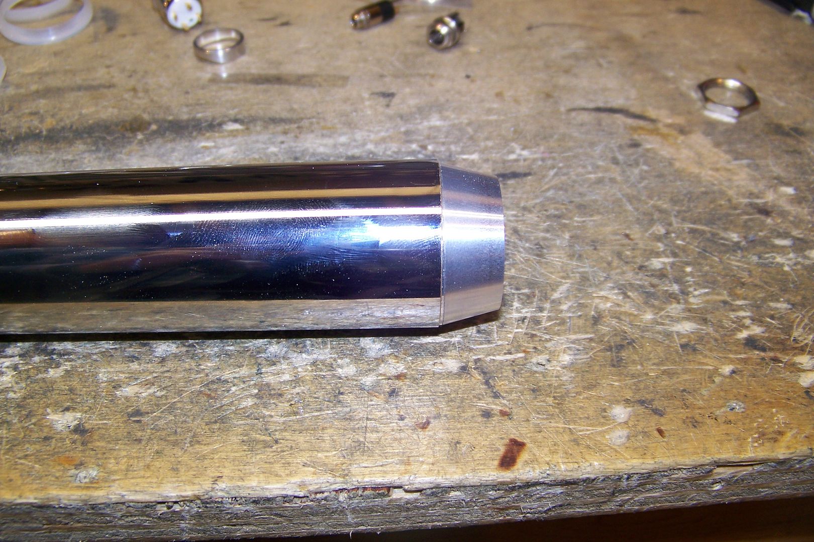
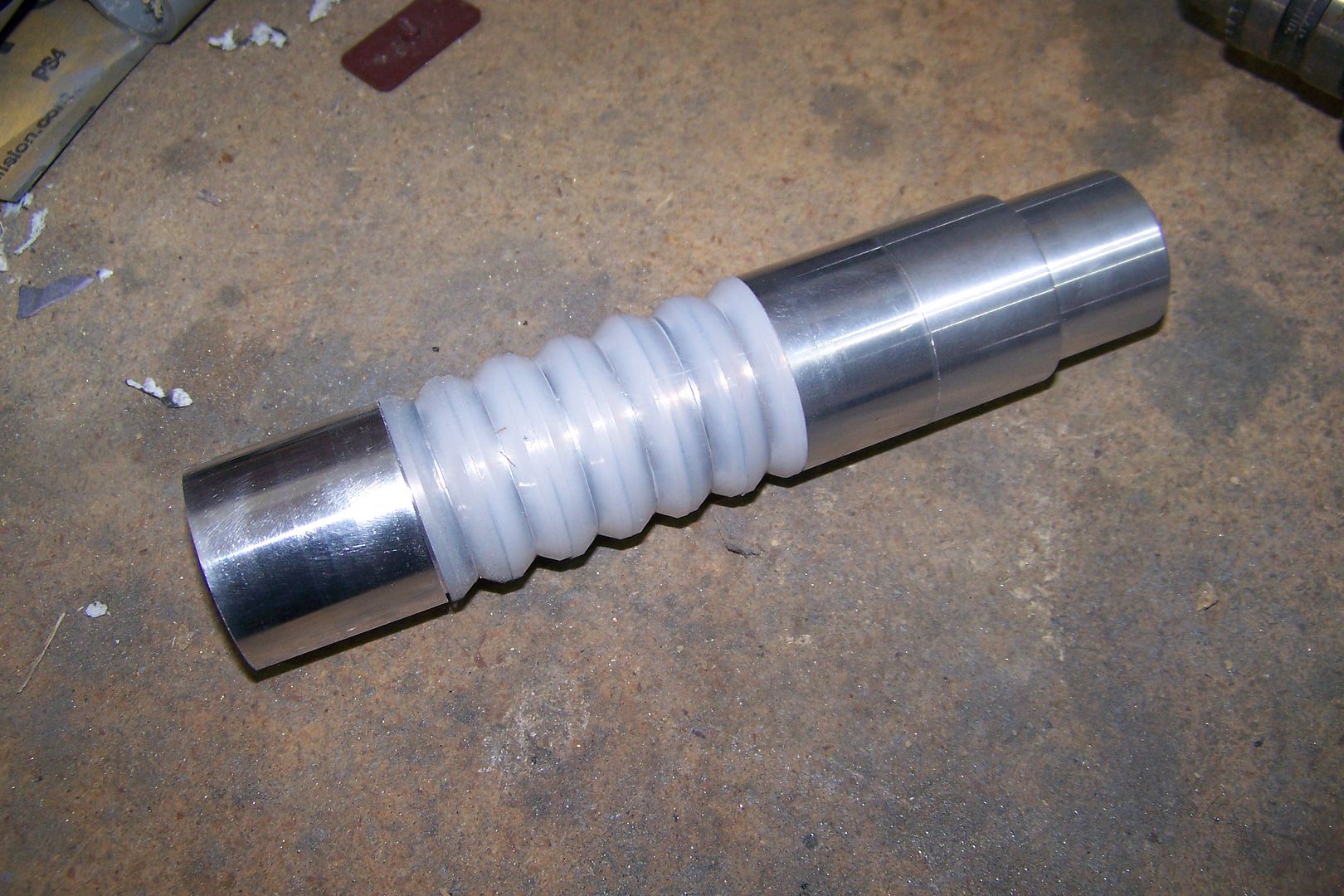
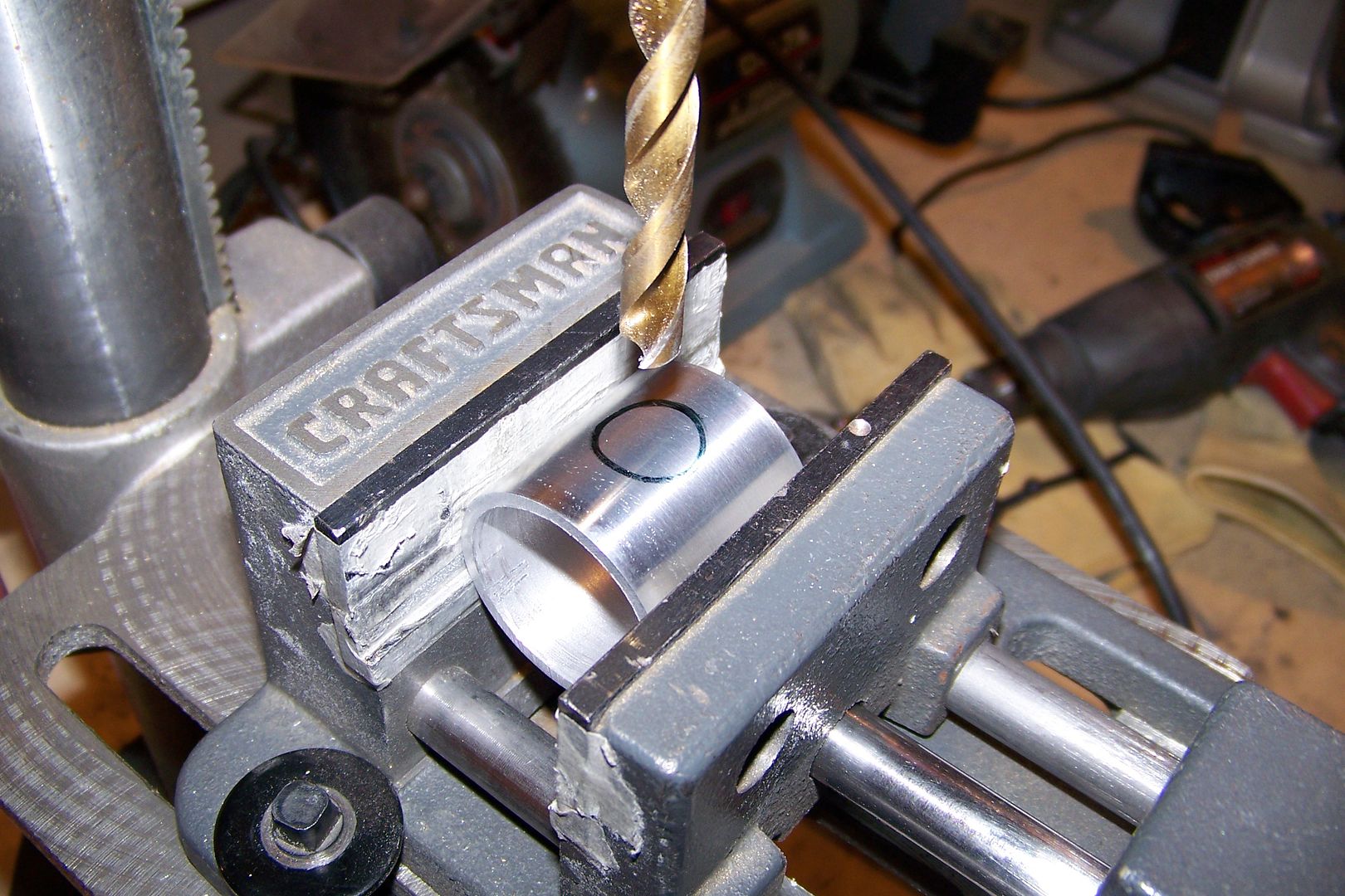
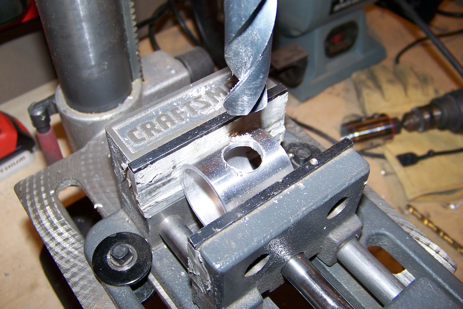
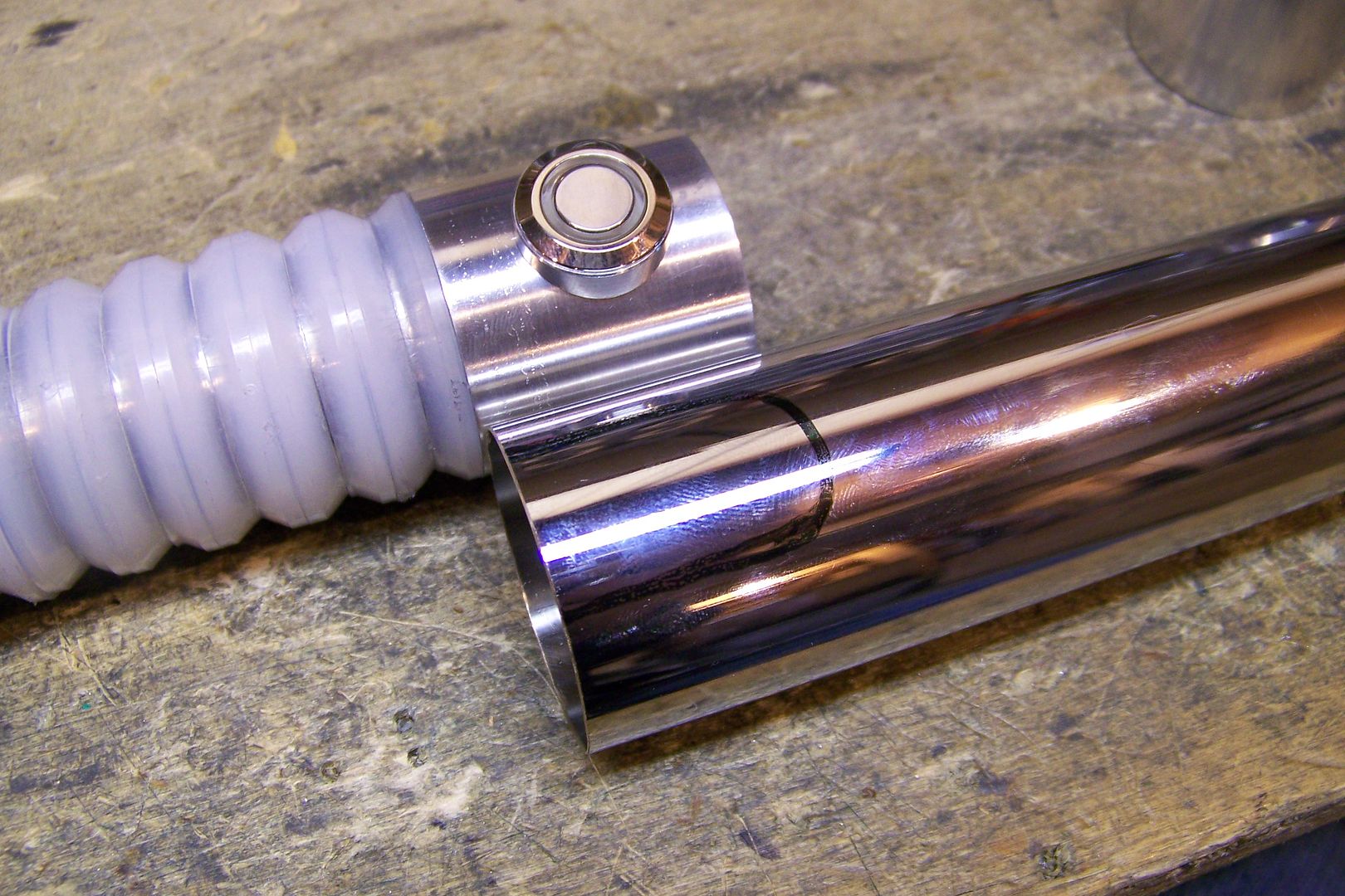
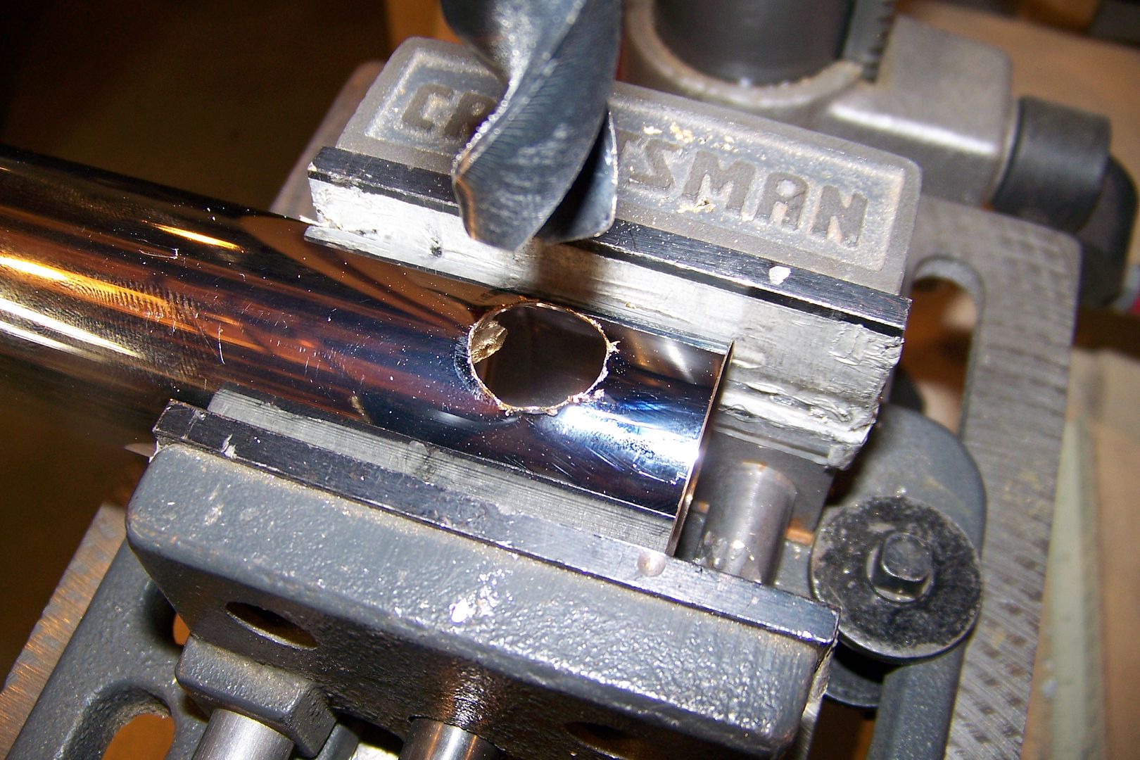
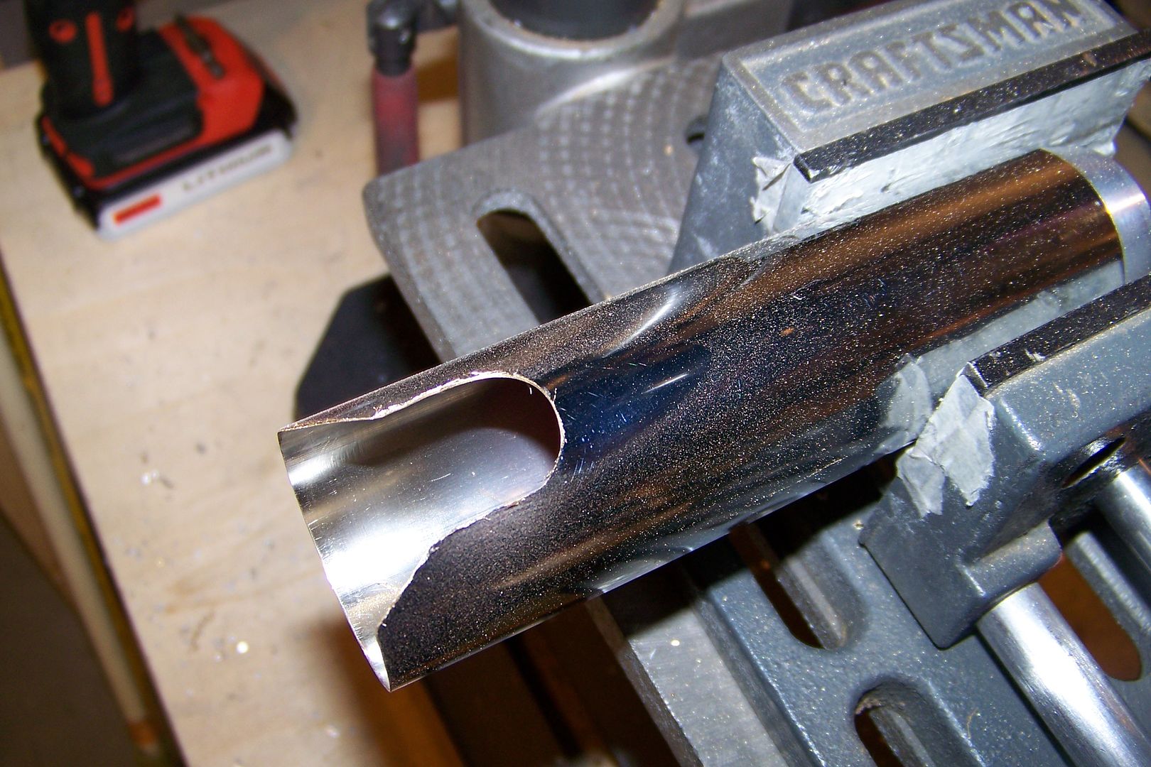
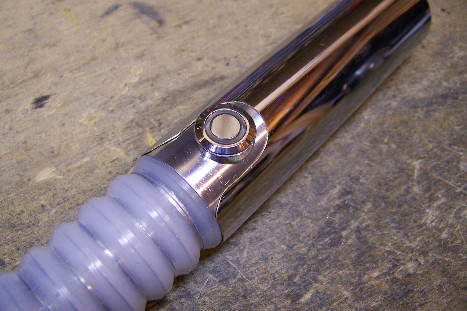
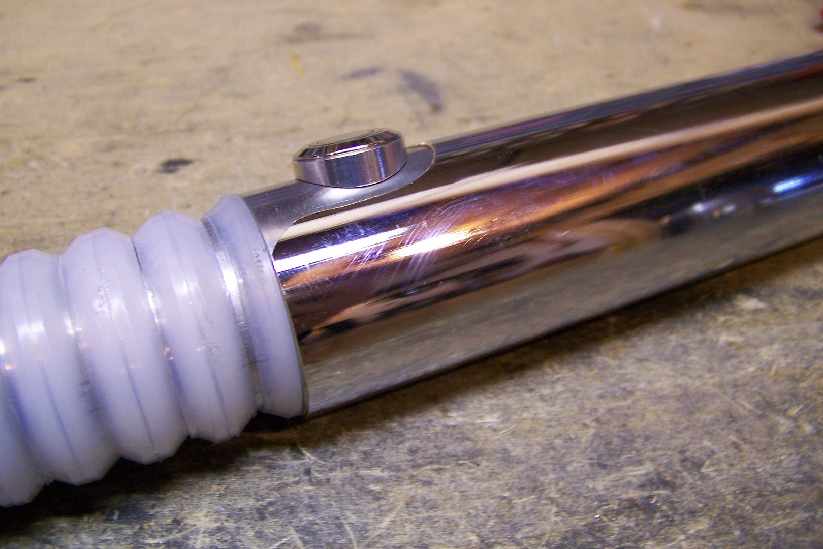
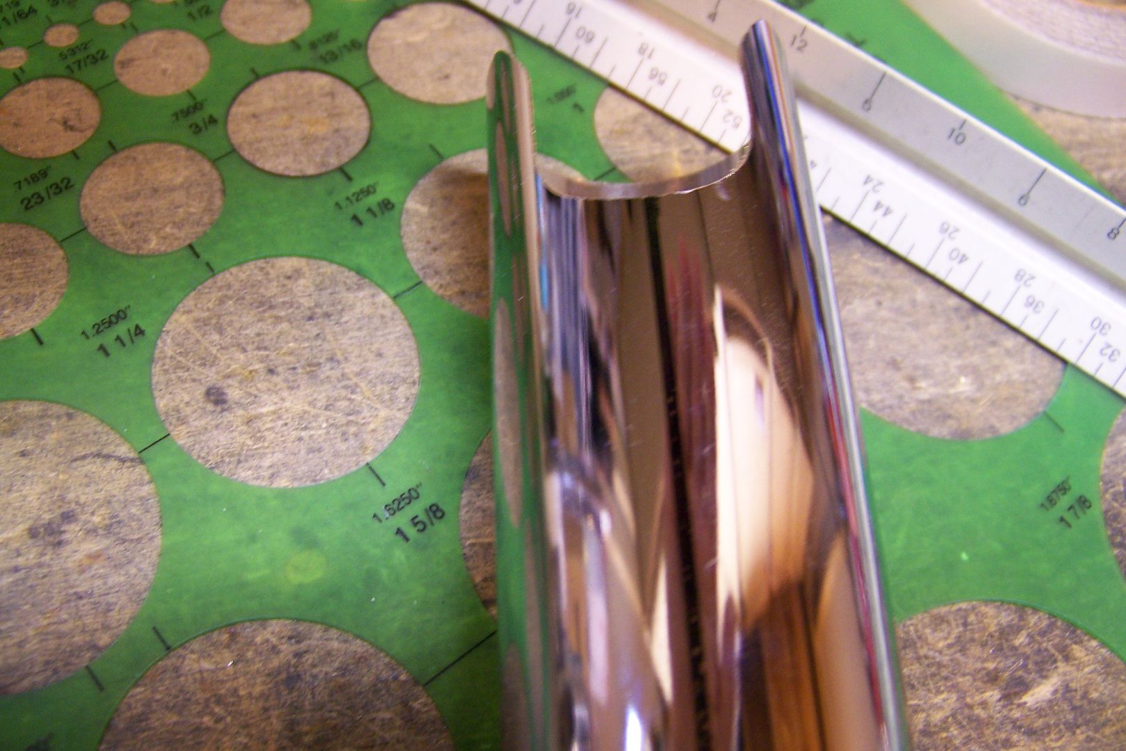
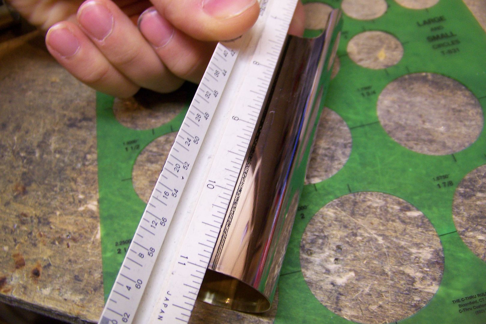
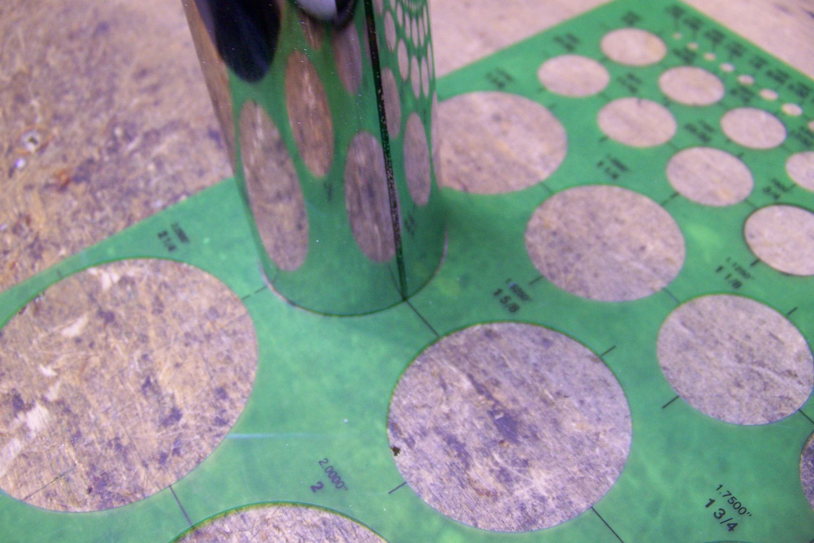
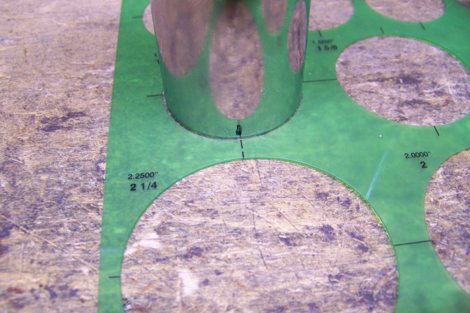
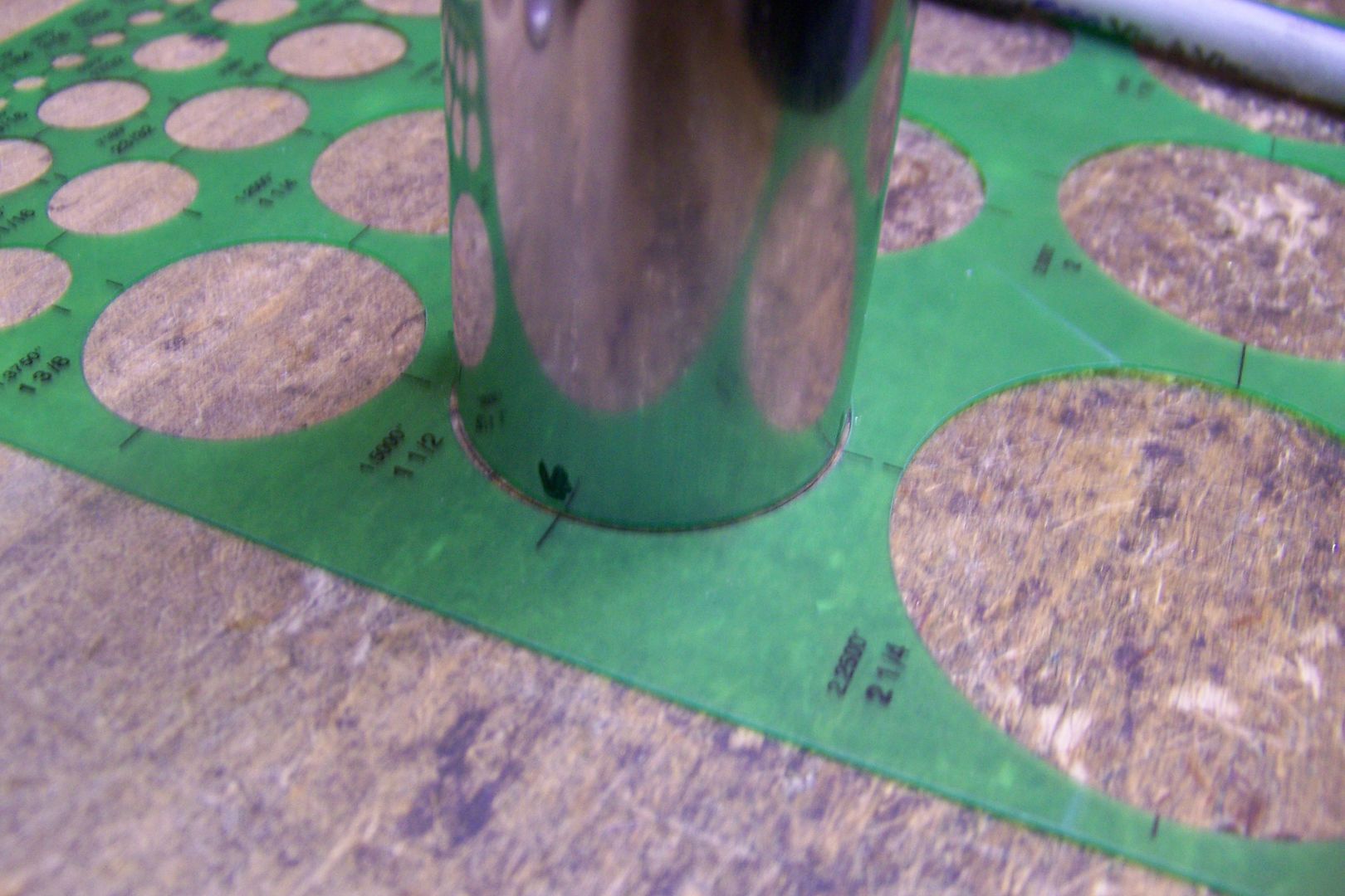
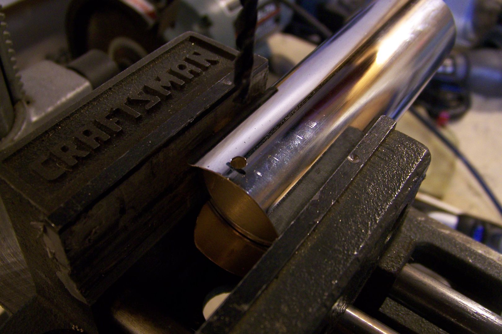
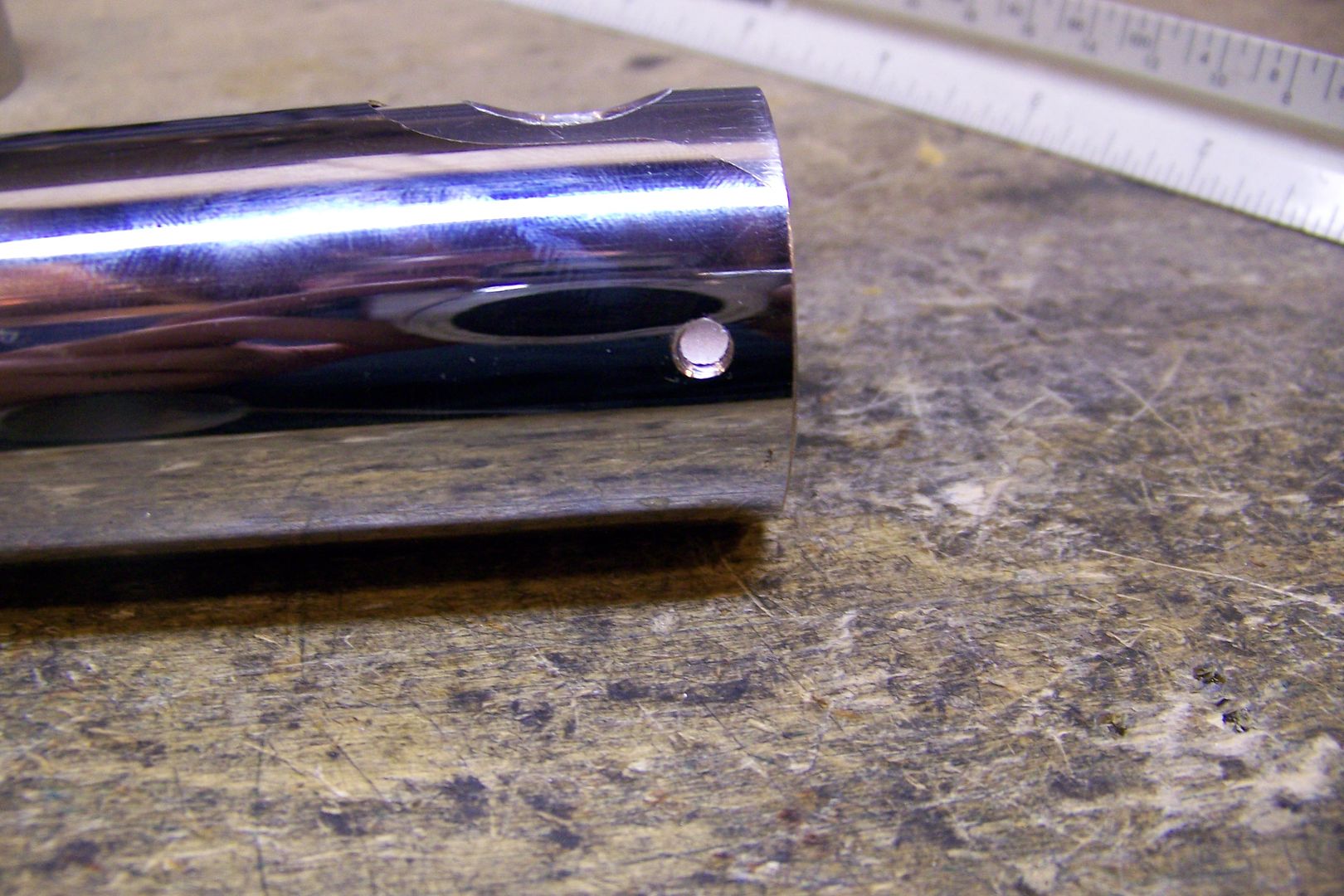
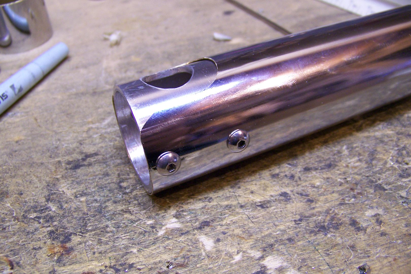
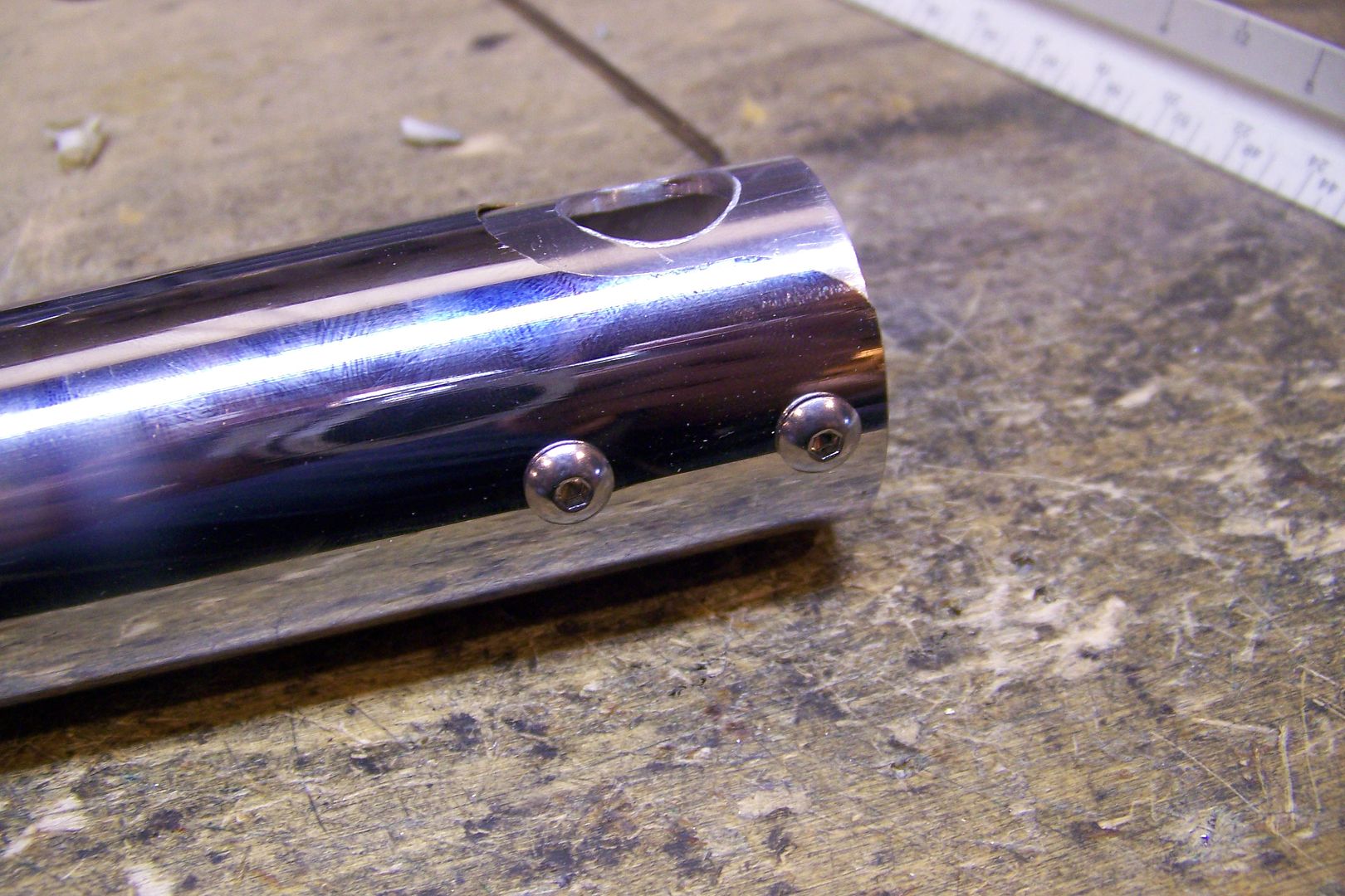
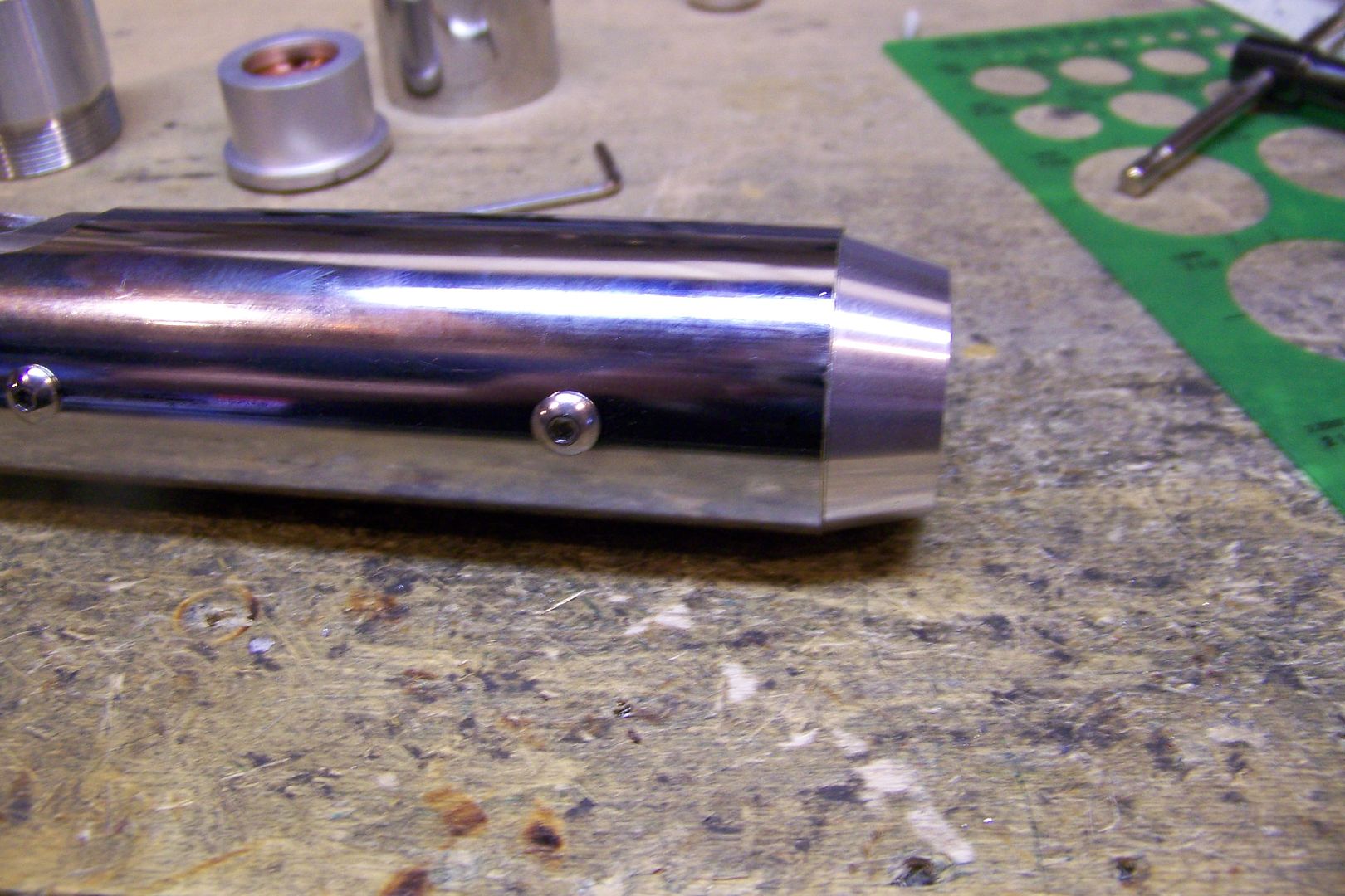
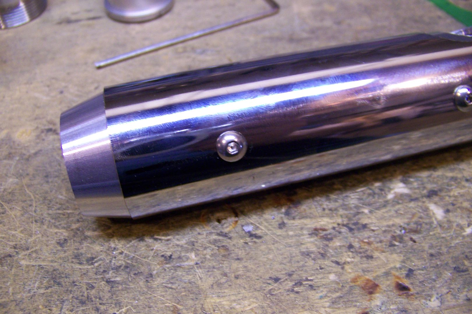
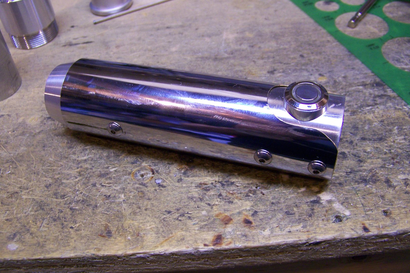
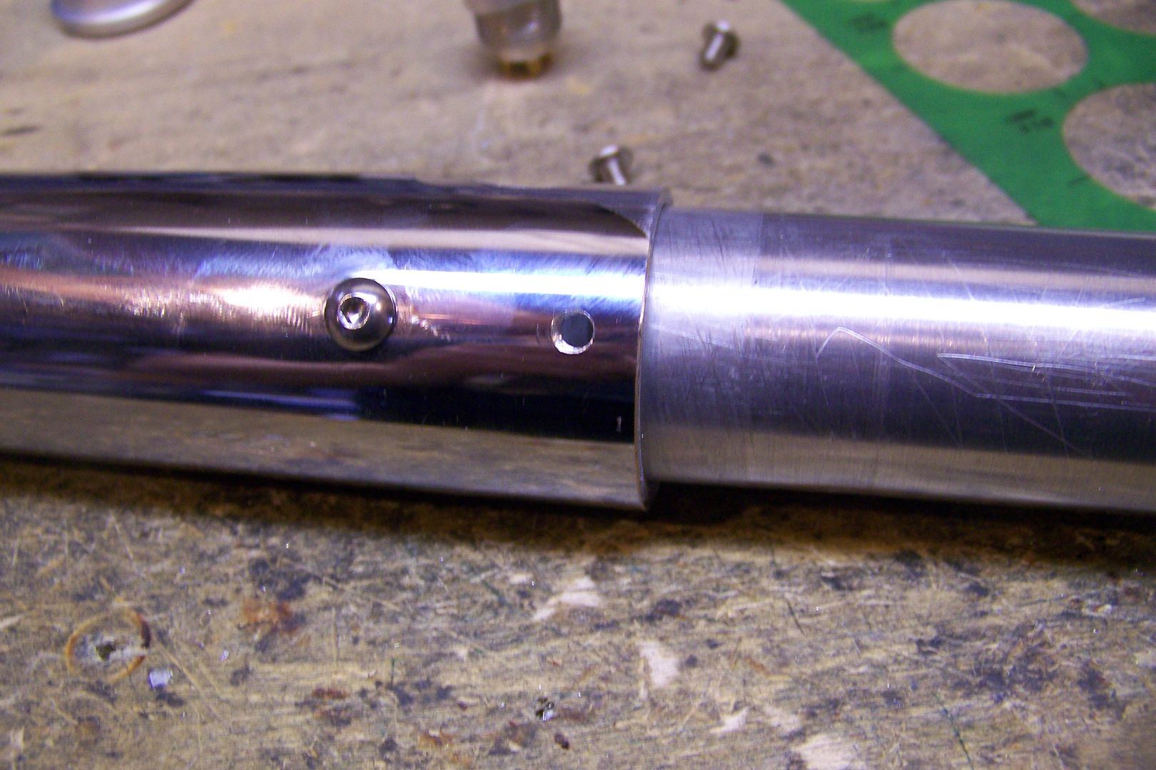
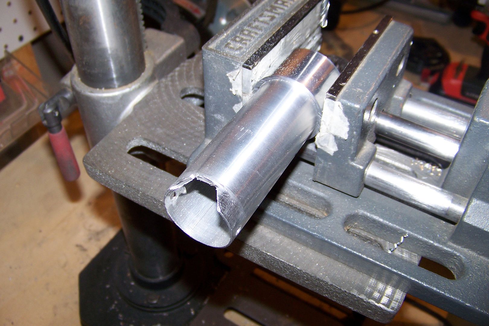
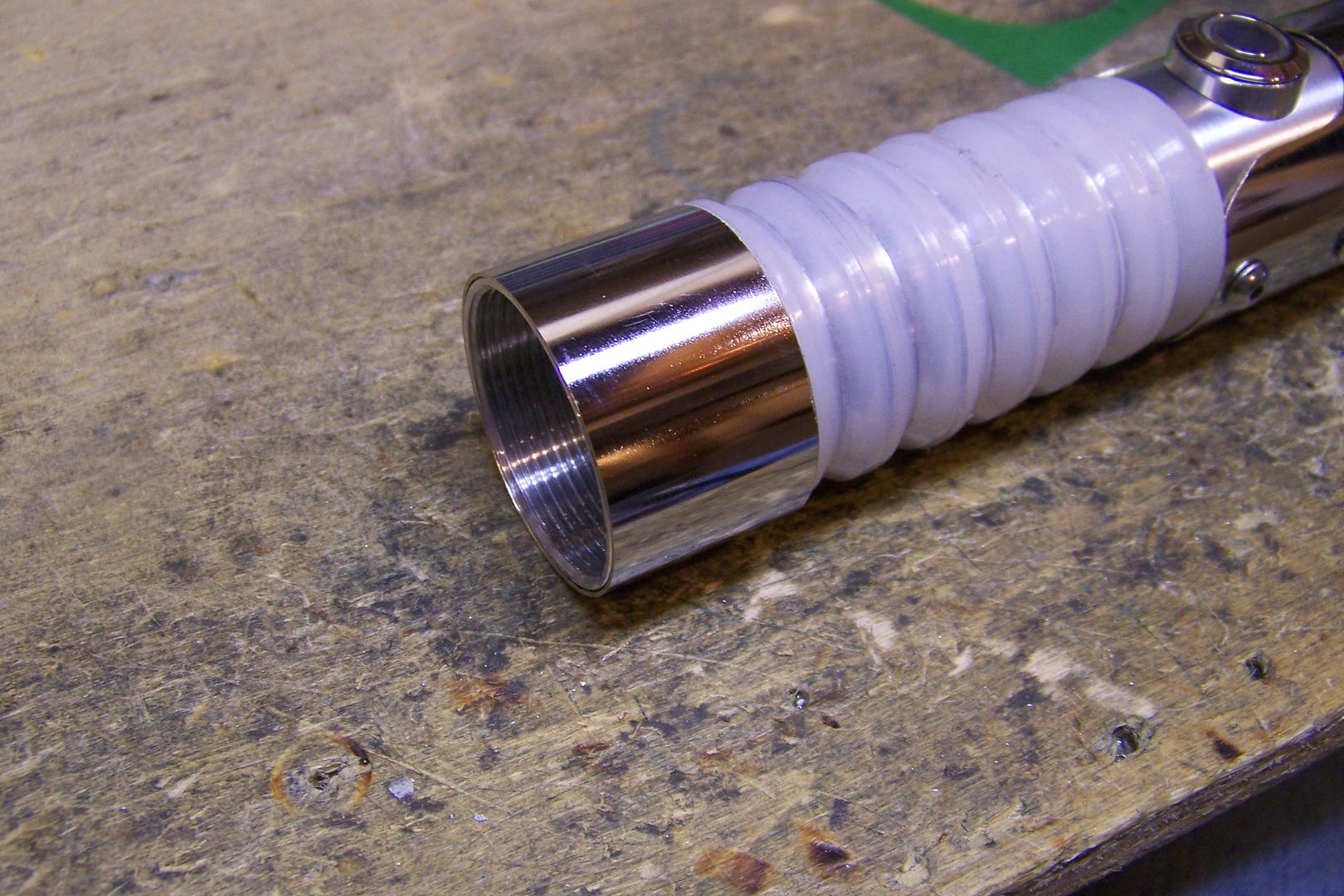
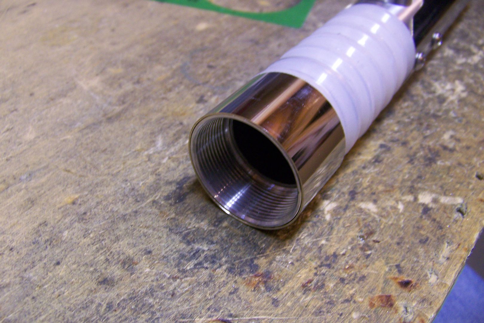
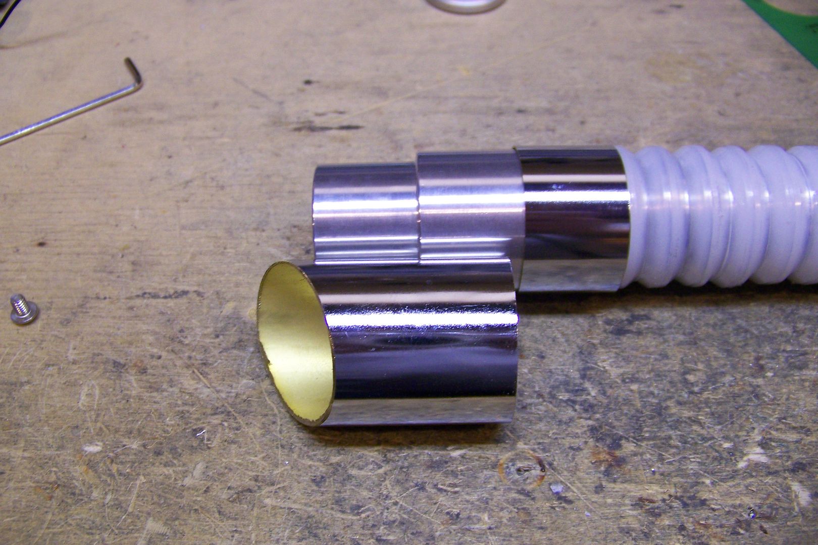
This last piece is the main piece. The chrome tube will serve as both the rear section of the hilt body and also will be used to make the emitter sleeve/shroud.
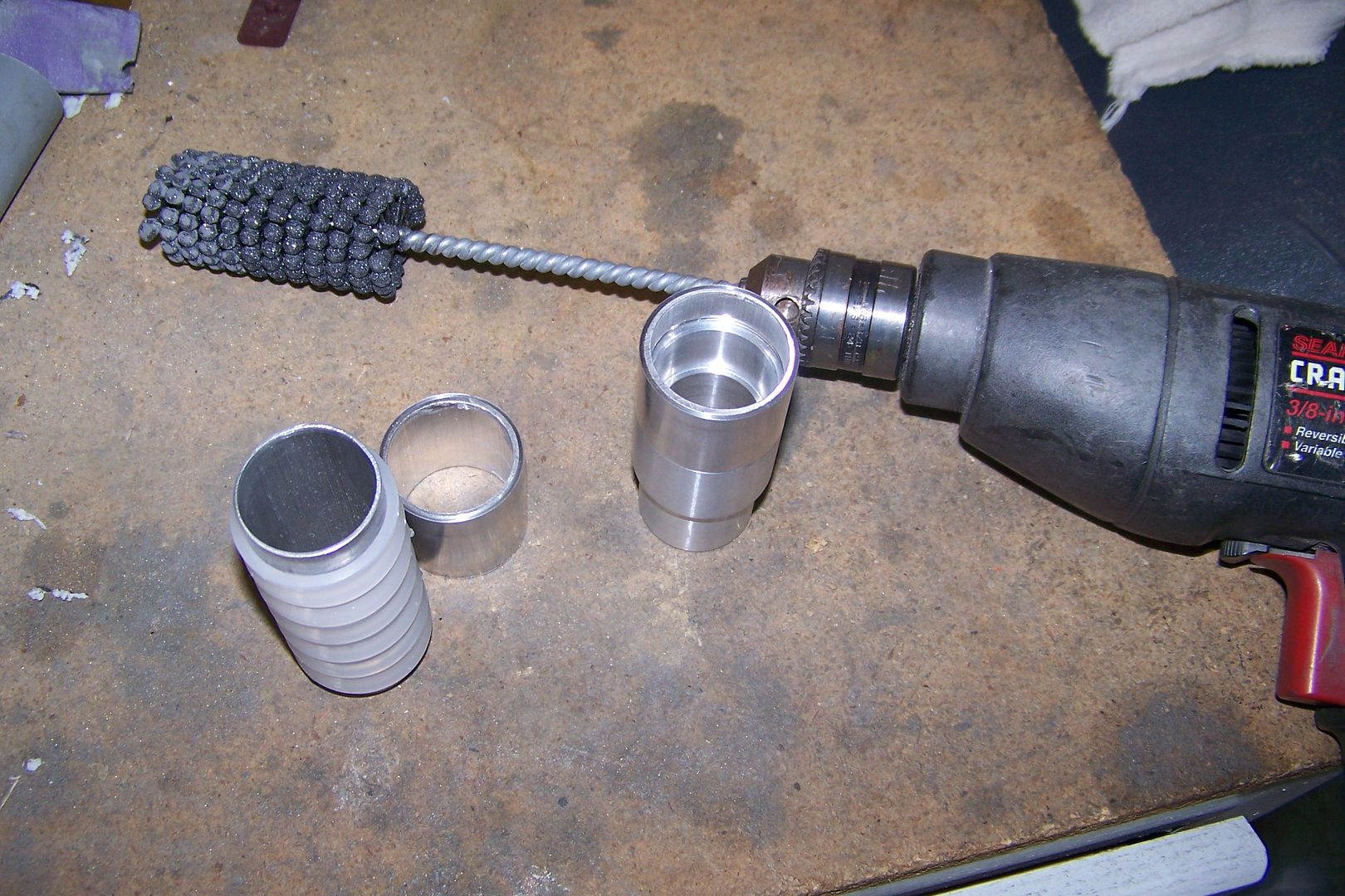
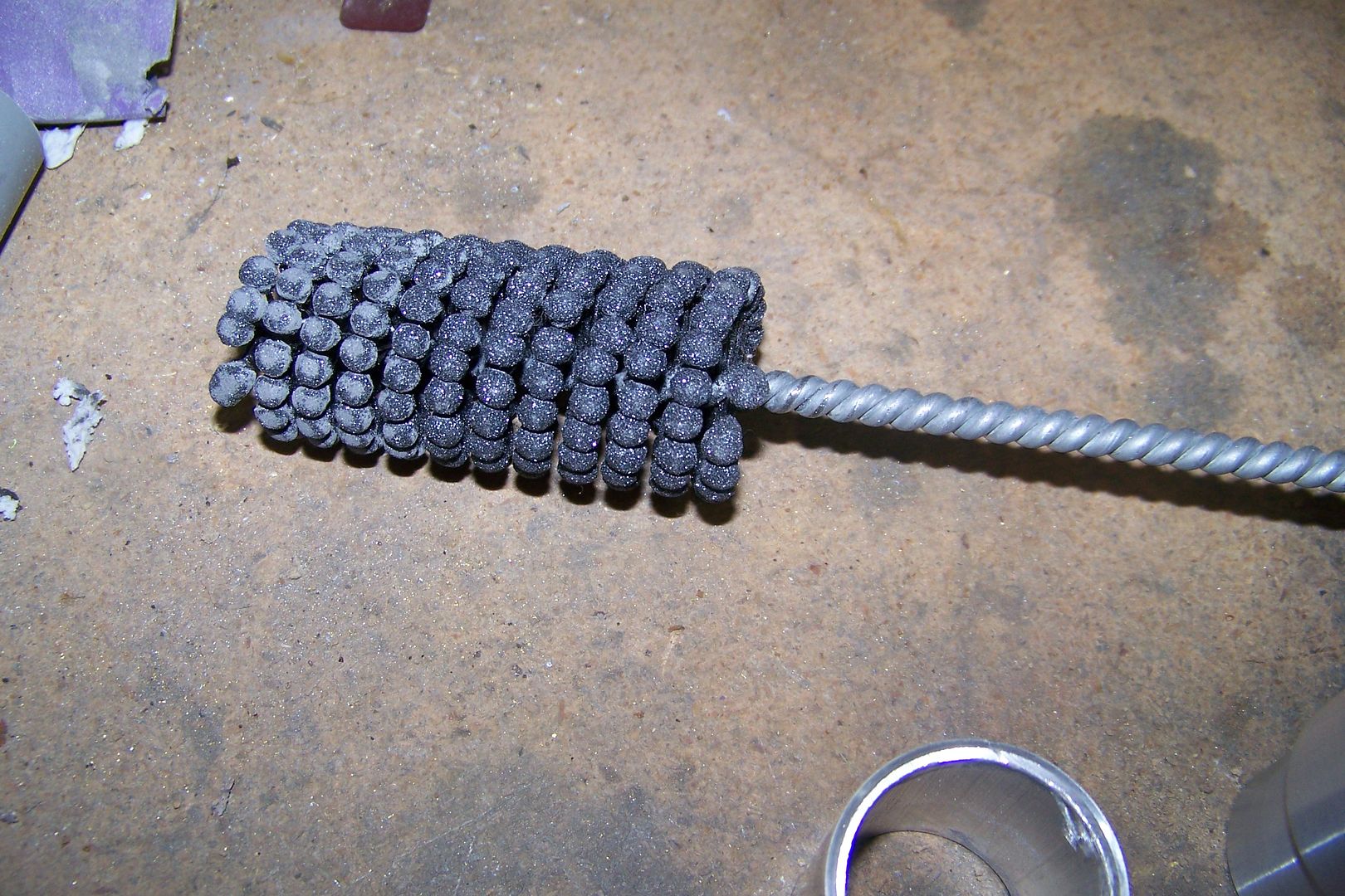
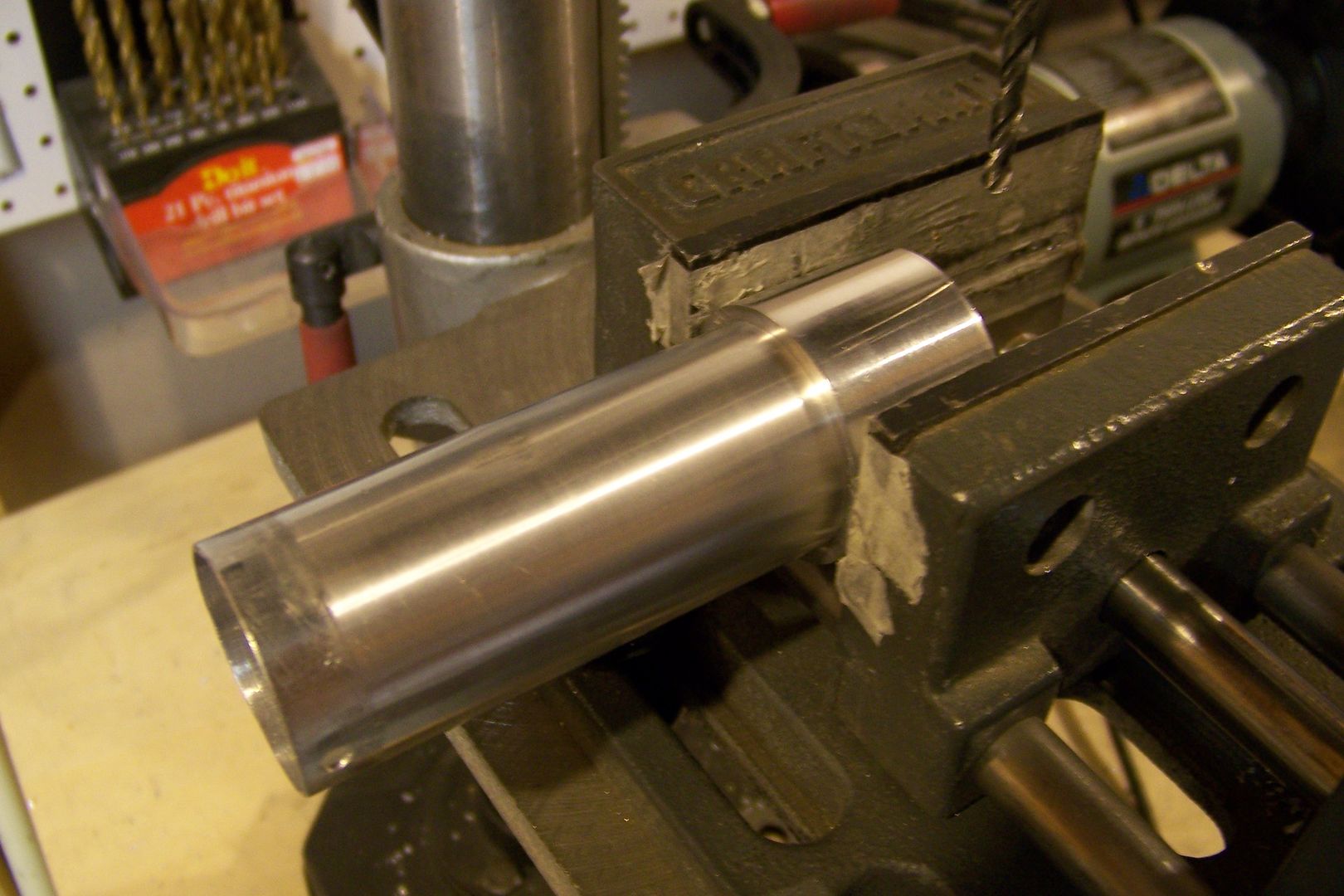
Cutting and drilling has already commenced, and I will update this as work progresses.


 Reply With Quote
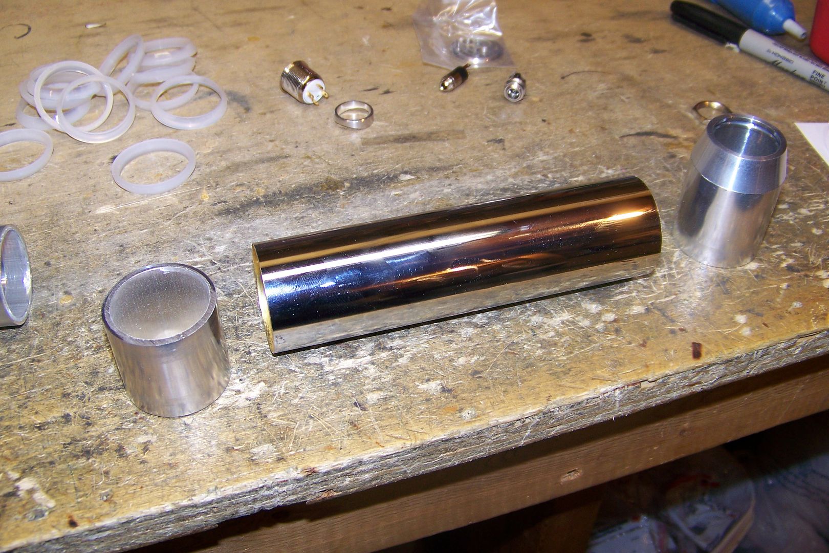


Bookmarks