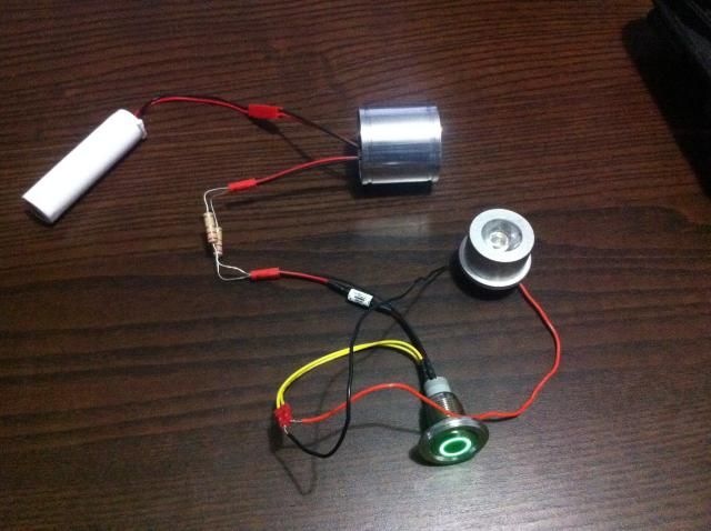
I finally got it to work! But for the record, the first pic is the wrong set-up that we tried to work with. I knew there was something wrong but who am I to argue with a PhD
This set up, which I suggested, essentially follows the basic direct drive set-up, but then the LED in the switch does not work:
Here is the version where all parts work:
Battery to charge port. One wire from charge port to LED. One wire from charge port to switch. One wire from switch to LED. Placed resistors on the switch's entry and exit wires but one would be enough, I think. Then I connected the switch's LED wires to the wires coming out of the recharge port, keeping the colors the same. Now all I need is a couple more long wires and some solder then some hot glue to insulate things.
I said who was I to argue with a PhD? I argued, and won!


 Reply With Quote
Bookmarks