Page 3 of 4 FirstFirst 1 2 3 4 LastLast
Results 21 to 30 of 39

Thread: Help wanted - Sourcing Parts in UK/Europe troubles, advice and general pointers

  1. #21
    Council Member
    Jedi Master
    FenderBender's Avatar
    Join Date
    Jul 2008
    Location
    Earth System - Rhode Island
    Posts
    1,531

    Default

    Quote Originally Posted by v1b1n View Post
    I have a few questions
    Accent LEDs all have their own resistors as do Power LEDs I see where PLI goes etc
    I uderstand what things need to be bridged now etc

    1) There are two Grounds on the board, do they both function the same, do they have to wire as in manual or can I mix and match between the two? There are many ground spots on the board, and there are two types of grounds on Plecter boards: signal grounds and power grounds. DO NOT MIX THE TWO.
    2) Can I wire the rumble motor to the FoC on top connections so it only runs on FOC, if not how is it wired to FoC, IF you are using CF7, you can wire the rumble motor to the 4th channel (with resistor) and set that channel to only come on during FoC. If you wire the motor to any of the other channel, it will be on if you do any kind of color mixing. The board won't distinguish a motor from an LED.
    3) Can the rumble motor be wired to Blade Lock too? Same as above.
    4) The Power indicator LED can this be wired to the power button instead of dedicated LED Yes.
    5) Does rumble need LED, i assume it shows activation of rumble, I am guessing it needs to be separate to power LED Huh?
    6) Does PLI need any other circuitry like residter or Pex or is it all built in PLI is a software function and designates all or part of the 8 accent LED pads for this purpose (on CF), only resistors are needed for the LEDs themselves.
    7) SMT resisters do not need to be calculated? instead you restrict the LED used? or is that just an example? if 603 are used what does that do from an electrictic point of view? more resistance, less brightness? what would that do? less amps? same voltage? or more of things? "As a space saver PC embeds the footprints for SMT resistors. The footprint is made for 0402 resistors like Farnell reference # 1357998 (22 ohm value provided as an example, user must do the math for the actually used accent LEDs – see below). 0603 resistors will also fit and they are easier to solder" Silber Serpent answered this one quite well. As for the 'easy to solder' part. No. I hate them, and I am fairly proficient at them after probably 150+ CF installs now. Think (literally, this is no exaggeration) about trying to use a needle to tattoo a flea and you'll have an idea of what a 0402 resistor is like to work with.
    What affect would wiring SMT Resistors do if no LEDS are wired? will they have no impact as not used? Why were they left off? to lower costs? Do People wire these instead of other resistors?
    9) I am guessing it is not viable to use connectors on everything due to space. I see there are a lot of wires in the manual terminating to the same places would be be better to connect 1 wire to the board and branch that one wire many times and use shrink wrap? I use quick connects on a lot of my CF builds. Makes testing outside the hilt easy, and installation of completed electronics much quicker. If you look around at Mouser and Digikey, you'll find a TON of small quick connects in many different configs.
    10) I am looking at extending a chassis and using acrylic disks rods and fibre optics to make a Crystal Chamber and use like a spacer with male threads either side to fix in the middle of the chassis so the saber can be unscrewed to reveal the chamber but that would need the main LED to be attached to the Chassis and not the Blade Holder else the wires could be twisted off or pinched so fixed would be better. If not that may be machine out part of the forward extension then hide the hole under a shroud This is subjective to how you want your build to go and is purely personal. However, I usually find a way to have most of the 'functional' stuff in a small forward section that doesn't move and have a mid to rear section that unscrews to reveal...whatever you want. A lot of us do this.
    11) MHS If I use extensions instead of main body (more stylish looking) can they me modified to house a button box I want to have R.I.C.E, recharge, Power and Aux all together (Activation box style 13) Yes, if you are willing to do the work. YOu could ask Tim to do it for you, but he would have to have a clear and concise plan of what size holes and exactly where you want them.
    12) Can the recharge port be wired to work without Kill key? No. This would be bad.

    I am getting closer to pricing up parts, the Builder is a Nice tool but it does not display all parts, how do I discuss any customisations for holes or machining the MHS parts as the options in store will alert that changes are wanted but not what, do you just order then discuss quote after or do I need to customise myself? I have questions about chassis parts also
    You reference Goodman a lot. I can tell you, from personal experience as I had almost every single one of his creations come through my hands, he was unique. He had an eye for fitting things and doing things that most people don't have. He also had all the time in the world to dedicate to each project and most of them took him MONTHS to do, even with all the machines at his disposal. Don't be in a hurry to rush this, you'll only fail harder. Also, most of his builds with the G-Core were NOT RGB color changing and many didn't even have FoC as he used simple coax quick connects on a lot of his LED modules that he made to facilitate the removal/reveal of the G-Core. Also, and this is a 'personal' thing for me, the electronics were not always secure in a manner that I would accept inside the core. It was great art, and genius at that, but I wouldn't attribute any more to it.

    If you're new, please take the time we all consider just as precious as you and READ!

    GET LATHED!

    Official BMF and LORD OF THE STRINGS

  2. #22

    Default

    Quote Originally Posted by FenderBender View Post
    Think (literally, this is no exaggeration) about trying to use a needle to tattoo a flea and you'll have an idea of what a 0402 resistor is like to work with.
    I love this statement. It's totally accurate.
    We all have to start somewhere. The journey is all the more impressive by our humble beginnings.

    http://led.linear1.org/1led.wiz for the lazy man's resistor calculator!
    http://forums.thecustomsabershop.com...e-to-Ohm-s-Law for getting resistor values the right way!

  3. #23

    Default

    Quote Originally Posted by Silver Serpent View Post
    I love this statement. It's totally accurate.
    What even with solder paste and a heat gun? But yes, that was my kind of thinking too, really, he expects people to solder those by hand lol, I wondered why they were not already added to the boards as the facility was made for them, is it cost? hassle? or does it impact the board in some way having these open circuits unused?

  4. #24

    Default

    I believe I already covered that. Which resistor would he add? The one that is appropriate for a 2.1 vf red LED? A 3.4 vf blue LED? A 3.0 vf green?

    Adding the resistors beforehand would be like locking the board to a single sound font. You would lose the ability to choose your accent LEDs.
    We all have to start somewhere. The journey is all the more impressive by our humble beginnings.

    http://led.linear1.org/1led.wiz for the lazy man's resistor calculator!
    http://forums.thecustomsabershop.com...e-to-Ohm-s-Law for getting resistor values the right way!

  5. #25

    Default

    Quote Originally Posted by FenderBender View Post
    You reference Goodman a lot. I can tell you, from personal experience as I had almost every single one of his creations come through my hands, he was unique. He had an eye for fitting things and doing things that most people don't have. He also had all the time in the world to dedicate to each project and most of them took him MONTHS to do, even with all the machines at his disposal. Don't be in a hurry to rush this, you'll only fail harder. Also, most of his builds with the G-Core were NOT RGB color changing and many didn't even have FoC as he used simple coax quick connects on a lot of his LED modules that he made to facilitate the removal/reveal of the G-Core. Also, and this is a 'personal' thing for me, the electronics were not always secure in a manner that I would accept inside the core. It was great art, and genius at that, but I wouldn't attribute any more to it.
    Do you mean these
    http://uk.mouser.com/ProductDetail/G...gpaMD9UtDr8%3d

    or these? have you tried these? these look perfect (I like the quick connect idea myself, not keen on end to end soldering)
    http://uk.mouser.com/ProductDetail/G...edDlh9IT2eM%3d
    http://uk.mouser.com/ProductDetail/G...sr3GolU8C1o%3d

    5) Does rumble need LED, i assume it shows activation of rumble, I am guessing it needs to be separate to power LED Huh? - >> see page 33 of manual, could you wire power led to this as well or instead (I am guessing the power putton would be FoC )

    Yes I mention G-Core because it is very artistic and in part could be simplified and adapted to hide/tidy inside the Saber, there is a guy who developed things using 3D Printing, it serves as insulating against damage and noise/rattles, I am not keen on the idea on securing to batteries and can see a problem, board on battery touching speaker = false triggered sounds

    There is a Sanjuro
    http://www.fx-sabers.com/forum/index...2437#msg492437

    Yoda
    http://www.fx-sabers.com/forum/index...opics;start=90
    http://www.fx-sabers.com/forum/index...7969#msg597969

    And others I can't seem to find right now but you get the idea, using TCSS Chassis parts and maybe a short double male ext secured in the middle you can practical/secure and visual/pretty. you can get creative with buttons attached to chassis it needs to be in two parts the outside part will just be a plunger attached to the hilt otherwise there is the issue of space and wires (computer cases do this)

    If there can be two parts ie practical one end http://www.fx-sabers.com/forum/index...6786#msg596786 the other end pretty my only problems are the LED/emitter and Button section/wires baecause regular buttons mean wires and space and an issue with fitting it all in (this where the creativity obviously is needed

    I am full of creative ideas having seen what others are doing, they just need to be played with and developed, until searching for this post I had only seen the crystal chambers I hadn't realised Yoda was using extended Chassis already so my idea not as original as I thought but in short i am not keen on just cramming it all into the hilt twisting n leaving lose like some do

    I been research all this a lot over the last few weeks, I pretty much haven't done anything else
    The idea is to map out the most complicated fully loaded build possible on paper piece it together virtually as a learning process

    Realistically due to limitations in stock my first build will likely be either a empty hilt or a no thrills NB set-up n focusing on the how to be tidy, hide wires and make it secure either play around with chassis or just get an all in one holder for the experience of soldering an throwing a saber together
    Last edited by v1b1n; 10-20-2014 at 12:44 PM.

  6. #26

    Default

    Quote Originally Posted by Silver Serpent View Post
    I believe I already covered that. Which resistor would he add? The one that is appropriate for a 2.1 vf red LED? A 3.4 vf blue LED? A 3.0 vf green?

    Adding the resistors beforehand would be like locking the board to a single sound font. You would lose the ability to choose your accent LEDs.
    That is what I was wondering
    1) If they were versatile enough to deal with various as you demonstrate above
    2) If it meant certain specific LEDs could only be used

    I saw a diagram using Power extenders instead but that was to split RGB main LED and additional RGB for the Crystal chamber, I thought it creative (obviously an older board)
    I guess the pex is just a regulator sending power where it is needed
    I guess this why people solder in line resistors
    I saw some rumble motors using Pex and others using resistors, guess Pex just more efficient, it still confuses me though you follow the manuals, draw it out then see wiring diagrams which do it very different and confusions set in once more lol

  7. #27
    Council Member
    Jedi Master
    FenderBender's Avatar
    Join Date
    Jul 2008
    Location
    Earth System - Rhode Island
    Posts
    1,531

    Default

    You 'can' use the wire itself for the accent LEDs to bridge the pads on the CF thus eliminating the need to use SMD resistors and instead use inline resistors. It works fine. My comment about hating 0402's was not in any way a criticism of the board design, 0602's are much easier to solder and work fine there. Plus, it should be a sort of 'right of passage' to have the skill to be able to do those pads without messing anything up. This is why most people start simpler, to learn the necessary skills and perfect them.

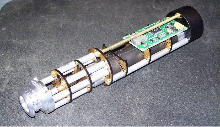
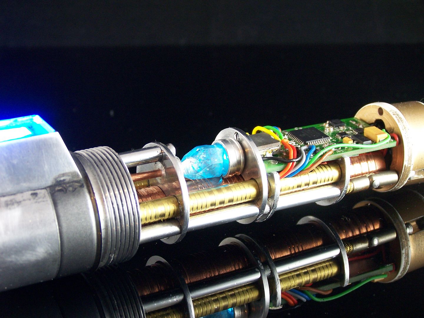
    No, your idea for a 'skeletal' chassis is not an original one. YODA has been making his Graflex chassis that way since 2006/2007 and have just gotten 'prettier' and more efficient. Many of us utilize that design for holding electronics and it works quite well. My Starkiller chassis was done that way to facilitate a tidy and repeatable install so I wasn't reinventing the wheel 30+ times:


    I have also done it several times in customs as well, sometimes with crystal chambers, other times without:


    If you're new, please take the time we all consider just as precious as you and READ!

    GET LATHED!

    Official BMF and LORD OF THE STRINGS

  8. #28

    Default

    Quote Originally Posted by FenderBender View Post
    You 'can' use the wire itself for the accent LEDs to bridge the pads on the CF thus eliminating the need to use SMD resistors and instead use inline resistors. It works fine. My comment about hating 0402's was not in any way a criticism of the board design, 0602's are much easier to solder and work fine there. Plus, it should be a sort of 'right of passage' to have the skill to be able to do those pads without messing anything up. This is why most people start simpler, to learn the necessary skills and perfect them.


    No, your idea for a 'skeletal' chassis is not an original one. YODA has been making his Graflex chassis that way since 2006/2007 and have just gotten 'prettier' and more efficient. Many of us utilize that design for holding electronics and it works quite well. My Starkiller chassis was done that way to facilitate a tidy and repeatable install so I wasn't reinventing the wheel 30+ times:


    I have also done it several times in customs as well, sometimes with crystal chambers, other times without:


    Yes that is what I figured regarding the surface mont resistors, what effect would using 602 have? Less current and brightness or is it subtle and unnoticeable?

    I have not seen them pictures before, very nice, I like those, is that a heatsink on the end? It's not a blade holder is it? Is that your work or yodas work? How the buttons done on those? Attached to chassis and hilt in two separate pieces? The other good idea could be metal contact points completing the circuit when the chassis inserted into the hilt

    Is the graffix dimensions much different to work with, it it easier or harder? I saw parks and the old MR ones look very similar guess there are a few making those, I obi WANs saber best out of the original Sabers those hilts are expensive but then any with detail are, it's crazy how producing small numbers hikes prices so much.

    Going back to the surface mount components I saw a few interesting you tube videos on that one was using solder paste by hand and a heat gun but the more structured was was with a overlay for boards you spread the paste over the template and it makes perfect contact solder paste points, u apply the components with tweezers put the whole thing into an oven and the board components align themselves properly when solder melted, there was another cool trick where he ran the solder and iron across all, the solder only stuck where it was needed, the board repelled the solder, it was interesting to watch, you tube has some amazing stuff, like a scientist making a working saber from known technology (plasma sword) the battery needed does not exist but he talked about nano tubes and what scientists know so far about them, they recon 50 years to see nano batteries, it would revolutionise electric cars for sure, sorry I digress, thanks for the feedback, appreciated.

  9. #29

    Default

    There are only two aspects of a resistor that will affect the circuit. Resistance and Wattage. Physical size (0402 vs 0603) is not relevant to the circuit. It is relevant to how much room you'll have left in your hilt. The tiniest resistors will have a more restricted set of wattages. It's nearly impossible to find a 5 watt SMD resistor.

    I've done SMD soldering by hand. I don't recommend it for a beginner. Heck, I don't recommend it for an experienced smith, unless they *really* need the space. Feel free to try it if you want. Get some perfboard and a few dozen inexpensive SMD components, and give it a whirl. If you're like most of us, you'll feel it's more trouble than it's worth for a standard install.

    I've probably watched the same youtube videos. They make it look easy. In practice, it's not nearly as simple. I wish you the best of luck.
    We all have to start somewhere. The journey is all the more impressive by our humble beginnings.

    http://led.linear1.org/1led.wiz for the lazy man's resistor calculator!
    http://forums.thecustomsabershop.com...e-to-Ohm-s-Law for getting resistor values the right way!

  10. #30
    Council Member
    Jedi Master
    FenderBender's Avatar
    Join Date
    Jul 2008
    Location
    Earth System - Rhode Island
    Posts
    1,531

    Default

    As SS said, the 0602 is just easier to work with by hand, and has no impact on functionality. Yes, those pics are of my work. The one chassis is just that, a chassis with a crystal holder piece on the front. It is for our Starkiller saber. The bottom pics were from two customs we did a while back. Graflex dimensions are more forgiving yes, as they are 1.55" OD and around 1.4"ID (I'm speculating as it's been a while and I don't have one in front of me with my calipers.).

    If you're new, please take the time we all consider just as precious as you and READ!

    GET LATHED!

    Official BMF and LORD OF THE STRINGS

Bookmarks

Posting Permissions

  • You may not post new threads
  • You may not post replies
  • You may not post attachments
  • You may not edit your posts
  •