Thank you.


Thank you.
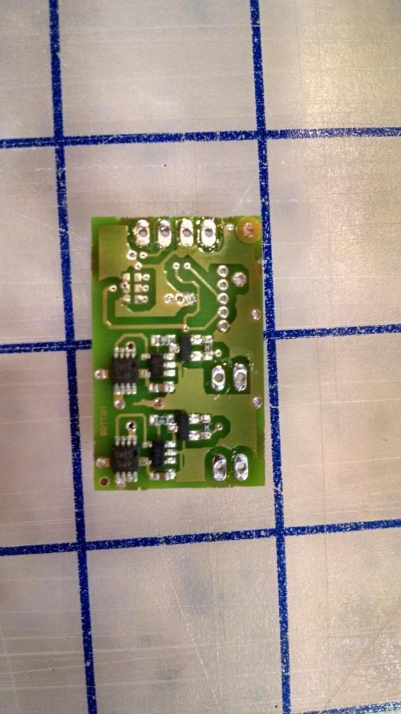
In case it helps, here are some pics of the CEx after I removed all the solder.


jumping to the discussionamong other things, are you sure you wired the CEx with +, channel 1, ground, channel 2
(if by mistake the ground is on pin 4 that could be it)
second thing is to set the color (current) of the dice by editing the file directly, so that we have RICE out of the question for now
Props Electronics
http://www.plecterlabs.com
Yes, that is how the pins are wired. +, channel 1, -, channel 2.
So far, I haven't even tried to use RICE. I've only been editing the config files.
Thanks for looking onto this, by the way.
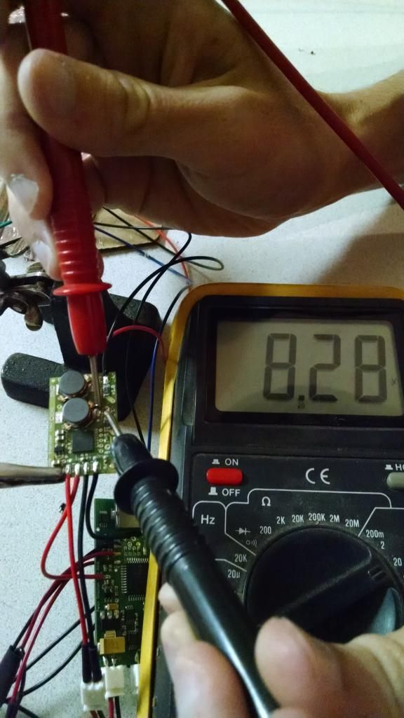
Maybe this will help. In this pic, the board has power, but the saber isn't on. The led2 (channel 1 on the color extender) is being given 8.2 volts (the voltage of the battery pack) even though no signal is being sent to it. I noticed this after I re-soldered everything and my green LED turned on after I removed the kill key. I figured this was bad, so I put the kill key back in right away, and noticed the module was smoking as I did so.
Last edited by cvsickle; 08-31-2014 at 05:46 PM.
from the unwired pics above, the board looks in good condition, however, if the board went smoking with the saber off, there's an issue, probably in the wiring. you might want to send me the board for diag / service. please contact me via the website
Props Electronics
http://www.plecterlabs.com
Well, the LED module was smoking with the saber of, because of the high voltage being applied to it. I should have been more specific. I'll contact you. Thanks again for looking at this.

Would you post your config file for bank 2?Originally Posted by cvsickle

Sure. Banks 1 and 3 are similar to this, bank 1 having 700 on led1 instead of led2, bank 3 having 700 on led3 instead of led2.
config.text:
// PCV3 Config - Shoto
led1=0
led2=700
led3=0
fled1=500
fled2=500
fled3=500
focmix=111
resume=0
shmrd=75
shmrp=6
shmrr=12
shmr%=50,80
focd=100
focp=10
focr=14
foc%=60,99
qon=0
qoff=0
flks=3
flkd=25
idlepulsing=5
idleled=3
override.txt:
## Override File
## vol - master volume (0-4)
vol=4
## beep - volume of beeps (0-127)
beep=15
## valsnd - 2nd touch for font selection (on/off)
valsnd=0
## switch - type of switch (0=NO,1=NC,2=MOM)
switch=2
## offp - APOP (on/off)
offp=0
## offd - power off delay (0-65535)
offd=250
## lc - low clash (0-102
lc=400
## hs - high swing (0-102
hs=200
## ls - low swing (0-102
ls=70
## i - overall sensitivity (0-99)
i=55
## swing - swing rate flow limiter (0-500)
swing=200
## clash - clash rate flow limiter (0-500)
clash=150
## lockup - time to engage lockup (0-1000)
lockup=250
 Posting Permissions

 Reply With Quote
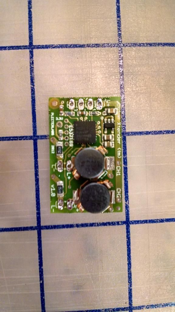

Bookmarks