Page 2 of 2 FirstFirst 1 2
Results 11 to 17 of 17

Thread: wiring check: NBv2 with recharge port, AV, LED, speaker

  1. #11

    Default

    Ok, so I finally started building. I ended up abandoning the recharge port because it would not fit with my current dimensions. So much for my planning. Didn't realize that AV buttons would block chassis, but you live and learn.

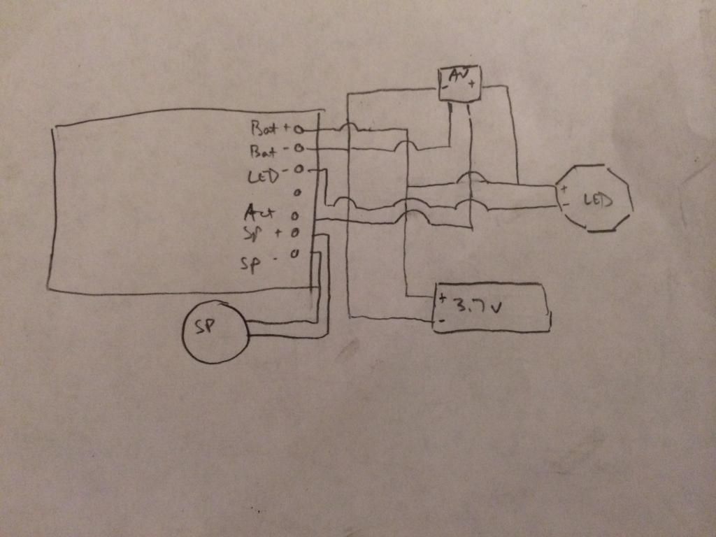
    So i modified my schematic to the following:


    I wired it up, then plugged in the battery. The AV light turned on but nothing else would. I rechecked my wiring. Everything looked good. Then I noticed the dynaohm for the AV MWS part from TCSS was on the red line. I wired black as positive. Doh. Okay, so I re-wired everything. Plugged it in, AV light comes on but nothing else. I check my wiring again and, like an idiot, when I re-wired everything I put the LED- wire on the momentary pad and vice versa. Doh ^2. I de-solder these and swap them. Plugged it in, it made a clash sound. I pushed the AV and I heard the ignition, the main LED came on, and there was a continuous string of swings and clashes. I thought it was just sensitive (all the board is sitting in its chassis on the table) so I hit the AV and it de-ignited.

    Awesome, it seems like it works. So I unplugged all my JSTs and loaded it in to the hilt. I plugged it in, the AV lights up and there is a clash sound. I hit the ignition, and I get nothing. I unplug all the JSTs and reconnect them, then do it again and I get the same result. I take the chassis out of the hilt and check all the wiring plus the connections, suspecting I pulled a wire loose in the cram-fu process. The wiring is as I planned and there are not loose wires. I deduce the following:

    1. since the AV light comes on, I know the power is coming out of the battery properly.
    2. since the speaker is making the same clash sound each time it is powered up, the board must be getting power and sending it to the speakers. That means Bat+ and Bat- as well as Sp+ and Sp- are wired correctly.

    That leaves the LED pad and the momentary. I figured that problem is probably the momentary pad since this is upstream of the LED. I de-solder this and re-solder it. I leave the chassis outside the hilt and plug everything in. Now, the AV lights, the main LED comes on for about 2 seconds, and I hear the speaker boot up. Then the main LED goes off, the AV Light is still lit, but hitting the AV button does nothing.

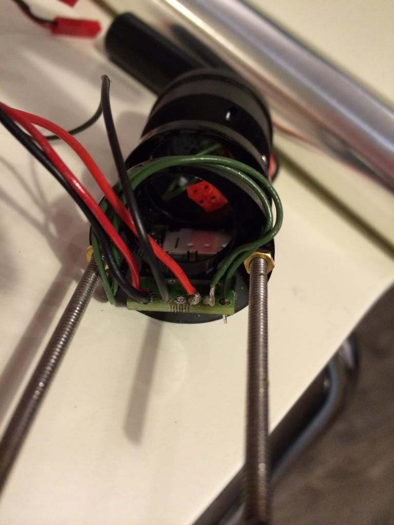
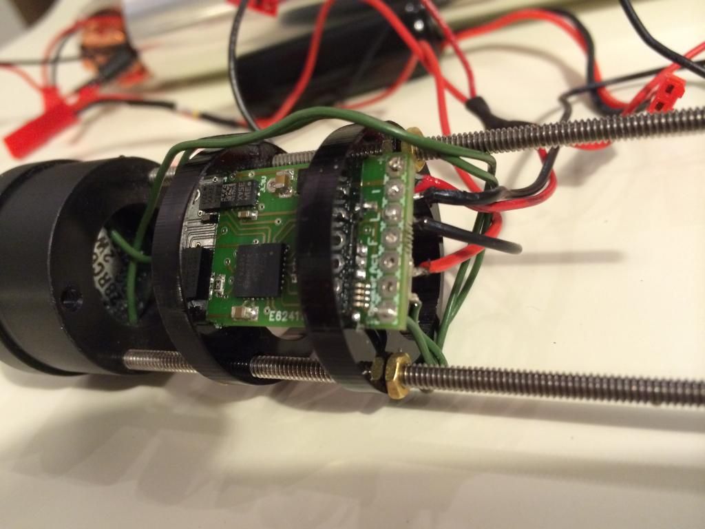
    I am at a loss now. Given the variable behaviour, it seems based on my reading that this suggests a short. I have looked over every connection on the board probably 15 times from both the top and bottom view. All of my wire splices that I did were tug-tested and shrink wrapped. I have included images of the board below. The only thing I can see is that the Sp+ and Momentary pads have a lot of solder and they are close, but the are not touching. This is actually a little uglier than right before my last solder-desolder as the soldering job was cleaner before i tried to re-do it, and it was not working properly then either.


    Thoughts? I appreciate any help...

    <yes, I realize I'm not the sharpest tool in the shed having had to re-solder literally 4-5 times because I can't follow a basic instructional...hopefully this did not damage the board...>
    Last edited by griva86; 09-02-2014 at 01:28 AM.

  2. #12

    Default

    Have you tried charging the battery? If you are experiencing erratic behavior (wild swing sounds, not turning on/off properly, etc), then most of the time your issue is a low battery. Charge it to full and then see how it works.

    You also have too much exposed wire on those connections. I would try to redo the ones with exposed wire and keep the exposed part as short as possible.
    We all have to start somewhere. The journey is all the more impressive by our humble beginnings.

    http://led.linear1.org/1led.wiz for the lazy man's resistor calculator!
    http://forums.thecustomsabershop.com...e-to-Ohm-s-Law for getting resistor values the right way!

  3. #13

    Default

    Battery charge was fresh and I tried a second battery same effect. I am puzzled.

    When you say that there is too much exposed wire, are you talking about exposed wire sticking through the contact pad hole or too much wire where it has been stripped on the top side of the board, like wires 1,2, and 5 above (from top to bottom, 6 and 7 being the green speaker wires). I was trying to strip less (like 2-3mm) but the wire cover was melting when I was soldering anyway, so I thought it would be better to control the removal of the wire cover...

  4. #14

    Default

    A few things to help with that:

    After you strip the insulation from your wires, pre-tin the exposed wire with a bit of solder. Then you can trim the wire to just long enough for a proper connection.

    Pre-tin the pads as well, though they've likely got enough solder on them now.

    If the pad and wire are both pre-tinned, then it should only take a second or two to make the connection. If it takes longer and the wire insulation is melting, then you need to use a hotter iron (or let your iron heat up more). It's counter-intuitive, but a cold iron will burn things more easily than a hot one.

    The long exposed sections of the wire connected to the board could be touching just enough to give you erratic behavior. Everything else looks to be isolated enough that touching the hilt isn't a problem. If you have a recharge port, check that carefully as well. Those are a common source of grounding to the hilt.
    We all have to start somewhere. The journey is all the more impressive by our humble beginnings.

    http://led.linear1.org/1led.wiz for the lazy man's resistor calculator!
    http://forums.thecustomsabershop.com...e-to-Ohm-s-Law for getting resistor values the right way!

  5. #15

    Default

    Ah, thanks for the tips. The tip about tin-then-trim is great. I'll re-solder the joints to the board, just need to pick up some de-soldering wire to clean up a bit.

    So I included a video clip of the boot up now. Actually, the AV light is no longer coming on. The only thing I have done since the last description of boot up was that I add a resistor before the LED, which I had forgotten previously. This makes me think maybe something came loose in my connections. I currently have an X formation on the power line. The bottom right leg is the battery, the bottom left is going to the board, the top right is going to the AV switch and gives off a branch to the main LED (before the resistor to the AV), and the top left is going to the momentary switch. Is there any issue with this 3-branch formation? I would imagine not, as long as the connection is good.


  6. #16

    Default

    What chassis discs did you use in that picture? Is that just the NBv2 with 18650 chassis disc?

  7. #17

    Default

    Yes, that is exactly right. Works like a charm. I also have a sled from shapeways that I'm looking forward to trying.

Bookmarks

Posting Permissions

  • You may not post new threads
  • You may not post replies
  • You may not post attachments
  • You may not edit your posts
  •