Page 1 of 2 1 2 LastLast
Results 1 to 10 of 15

Thread: My first LED string blade - a progress diary

  1. #1

    Default My first LED string blade - a progress diary

    So finally I decided to follow the instructions of accomplished masters and build my own LED string lightsaber(blade). I've got a lot of invaluable hints and inspirations from this forum and could not wait to start. I would like to share my progress (still working on it), less in order to reinvent the wheel (there are a lot of beautiful LED string blades out there), but to get more valuable hints from you as I go along.

    I long pondered upon how to link those LEDs together, until I stumbled upon a good description in Erv's CF-LS documentation, honour where honour is due, thanks for Makoto-San and SlothFurnace for their tutorial on how to build the "arm buddies" type LED string. I also found a similar link here: http://www.waynesthisandthat.com/lightsaber.html

    I'd been researching the topic of how to modify the LED to get the most out of the LED string, including the different methods to shear off the dome for more even light emission radially. At the end I decided to go for a string using 5mm LED's as they are, I figured that if I was not satisfied with the results, I could still try again with a string of modified bulbs.

    But how to achieve a uniform and consistent LED string? At the beginning I had no idea what tools to use to bend the legs so that the process can be reproduced for >80 LEDs. I made a lot of measurements and came to the conclusion that the distance between the LED legs should be 6mm, bent at the lower end 10mm below the bottom of the LED. But how to make that 6mm and that 10mm bents consistent?
    It's only through purest luck ... ehem ... there is no such thing as luck, obviously the Force wanted me to find that pencil lead holder, whose shorter side just measured 6...


    Next step was to find a good jig to bend the straddled legs agt exactly 10mm. After some looking around over my workbench the Force made me gaze at my vernier caliper. I might have been in a Force induced trance, becaese I do not recall any more how I found out the way to bent the legs with the caliper, enough to say that at the end I used the inside small jaws to open them at 10mm and put the legs of the LED right through the jaws and bend them at the other side like this:


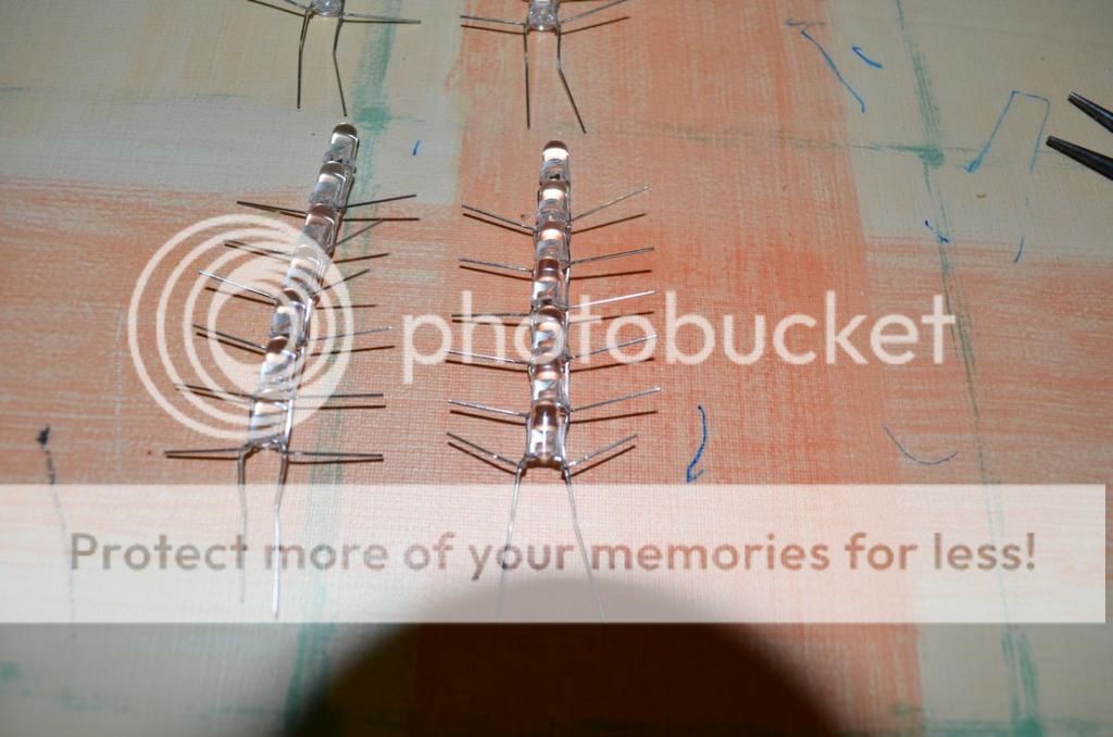
    After this I just followed the lighted part of the Masters mentioned above to link the bulbs together:

    With tweezers I bent the linked legs to the sides to lock the LEDs in place.

    Finally I had my small seqments, now it was time to think about how I was going to wire them... more to come as I progress.

  2. #2

    Default

    Now comes the fun part. After I had my first linked bulbes, it was time to make the first trial run on them. I connected 10 of them in paralell to see how bright they were and how much current they consumed (I used this type of LED http://www.led-tech.de/de/Leuchtdiod...LT-25_1_4.html, sorry, German side, but the main characteristics should be clear, 7000mcd max, that was going to be damn bright!!!).
    Well, I suspected this, still it was like to revelation to see that even 10 of these beasties consumed over 1A atmax voltage. Of course on the other side they were really damn bright, thanks God I used protective googles (I really wear them nowadays when I work with LED's for lightsabers, no joke). So I made the maths. For a 32" blade I needed 84 LED's. Even at typ threshold voltage it was going to mean ~6A...wow, no supply would give me that juice which also fitted into a hilt. Well, since I suspected this, I was afraid from the beginning that there was no way around building the string in what came to be known from SlothFurnace as a Serial class II. wiring. Since I had a Crystal Focus 6.5 LS in mind when starting this project, I calculated 6 segments with 14 LED's each, i.e. 7 in parallel, serialized.
    On the pic the segmens are put in a row and I already started there to put the first line of defence againt mechanical stress: shrink tubing:


    The terminals poke out like this, somehow a pity that both the + and - leads are on the same side due to the serialized wiring of the sub-segments, but the current consumed more than makes up for this nuisance.


    Now it was time to test the whole string the first time:


    I cannot wait to see this string inserted into a TCSS opaque blade with diffuser. I feel the Force already surging through it

  3. #3

    Default

    Are you using a resistor with these LEDs? These LEDs are rated to go no more than 20ma each. That means that if you were to connect 10 LEDs in parallel then they should only be using 10*20=200ma + however many miliamps the resistor uses. If you don't use a resistor when testing these LEDs, they will just try and consume as much current as they can get their hands on (ultimately damaging the LEDs). 10 LEDs in parallel should definitly not be using 1A of current. I could have misread your post so please correct me if I am wrong. Also if you buy more LEDs in the future, I reccomend that you try and get ones with a higher viewing angle than 20 degrees as I have heard that it seems to be more important than the mcd brightness. So if you were to buy LEDs with the same mcd but twice the viewing angle (40 degrees) than the LEDs would give off approximately twice as much light and more of it directed at the sides of the blade and not the tip of the blade.

  4. #4

    Default

    Hi Fungodude, thanks for your feedback. To answer your question, no, I do not use resistors, at the moment I supply the strings with a lab power supply at 6.8V (due to them having a max voltage of 3.4V). You are right with your maths, they should not consume more than 20mA, but diodes have a fuzzy exponential current/voltage curve and the 20mA applies to typ voltage. At that voltage the brighness is already higher than those of Habsro/MR and the current - with the serialized setup - is about 20mA I guess (those lab supplies are not that precise when it comes to metering currents). But I want a brighter blade! So I use the max rating of the diodes. I've also seen that above the typ threshold value the current consumed increases much faster than the brighness, so there is a trade-off somewhere.
    That with the viewing angle is a good point, thanks for pointing it out, it was not a parameter I considered so far (being my first LED string). If I get a 40 degrees LED, do I need less diffuser layers than with 20 degrees? Because that's (at this point and level of experience taht is) my biggest concern.

  5. #5

    Default

    Quote Originally Posted by Fungodude View Post
    Also if you buy more LEDs in the future, I reccomend that you try and get ones with a higher viewing angle than 20 degrees as I have heard that it seems to be more important than the mcd brightness. So if you were to buy LEDs with the same mcd but twice the viewing angle (40 degrees) than the LEDs would give off approximately twice as much light and more of it directed at the sides of the blade and not the tip of the blade.
    Would this still be a factor if you decided to sand or "drill" the tops of the LEDs? Some of the logs and journals I have read involve this technique to help better diffuse or direct more light.
    A fool speaks of what he knows while a wise man listens for what he does not.

  6. #6

    Default

    Quote Originally Posted by parsaver View Post
    Would this still be a factor if you decided to sand or "drill" the tops of the LEDs? Some of the logs and journals I have read involve this technique to help better diffuse or direct more light.
    Sanding or drilling the LED would help increase the viewing angle and ultimately make the lightsaber appear brighter (because more light is going out the sides of the blade). But if you were to take an LED with a viewing angle of 20 degrees and an mcd of 5,000 and drill it so that the viewing angle was 40 degrees then the mcd would be cut in half to around 2,500 mcd. This is because mcd is not the total amount of light coming from the LED, it is the intensity of the light. But it should also be noted that these calculations are not that precise because you could probably drill an LED so that more light was going out the sides of the blade and less light was going towards the tip (so light is not going equally in all directions). You really want the least amount of light going into the tip of the blade because it is pretty much just wasted light. I believe that the supernova blade's LEDs were designed to do this to waste the least amount of light as possible.

  7. #7

    Default

    Quote Originally Posted by Obi1 View Post
    That with the viewing angle is a good point, thanks for pointing it out, it was not a parameter I considered so far (being my first LED string). If I get a 40 degrees LED, do I need less diffuser layers than with 20 degrees? Because that's (at this point and level of experience taht is) my biggest concern.
    I would reccomend that you use the same diffusion system that the mr/hasbro force fx blades use (you can get all of those blade supplies except the foam diffuser from the Custom Saber Shop). I myself have not constructed my own blade yet so most of what I am saying is in theory or from what other people have talked about.

  8. #8

    Default

    Now it's time to make some progress Fongodude, thanks for your valuable hints, especially on explaining how mcd values relate to light intensity. I still do not pretend to undestand fully how to interpret this value, but I got closer to the right understanding now. That is what I like and value in this forum: as I go on with a particular build, I also learn a lot in the process.

    I was a bit ashamed to make fast statements about the current consumption of the first 10-LED string I had built, I did it because my measurement results were not at Hand, now I recovered them, I measurments from 2.4V to 4.2V (max of the 18650 battery cell) with 100mV steps, I do not want to copy in the whole table, just some corner points:
    <2.7V - no light, no current
    2.7V - 20mA (~2mA, however a simple table lab supply is not very precise when it Comes to metering currents)
    3V - 120mA (12mA/LED)
    3.2V - 230mA (23mA/LED, closest to the spec typ value)
    3.4V - 450mA (45mA/LED, this is the max threshold of the LED's)
    3.7V - 800mA (80mA/LED; typ voltage of a 18650)
    4.2V - 1.5A (150mA/LED)

    With the parallel Setup II. I measure ~1.5A with 84 LED's at 6.8V, that fits approximately (half the current per LED).

    Now back to the Progress diary: after having the LED string put together, next task was to try out the TCSS trans-white blade with diffuser:


    To be honest, I'm pretty satisfied with the outcome, even without LED dome modifications the blade is terribly bright!!! For comparison I made some pics with some of my other sabers.


    The topmost is an Ultimate FX (my first toy lightsaber), followed by an FX Obi-Wan, then the LED-string, then an MHS (still in construction, stripped of its shroud) with RGBW Cree single HP-LED. Same pic with lighting:


    Well, I guess there is no lightsaber which would not look good on a pic, definitely the LED string I've built overshines the 2 Hasbros easily. The Cree HP-LED is brigher at the emitter, but it looses intensity towards the tip. The LED string has a very homogenous light, same brigthness along the blade. I know that it could be improved, but as of now I seriously think that a if it were any brigher, it would be a serious threat to my eyes.

    I do not have photos (well I have, but nothing can be seen of what I wanted to show), but I also tried other diffusing methods, like putting the string into the transwhite without the diffuser, or a regular transparent blade with cellophane (used in my MHS with Cree HP-LED) or a transwhite from another vendor, result always the same: the single LEDs can be seen, disrupting the effect. So the diffuser is a must. Actually optic-wise I would not need an additional layer of diffusion, but to better protect the string from mechanical forces I will wrap a foam around the shrinktube mantle.

  9. #9

    Default

    Quote Originally Posted by Obi1 View Post
    3.4V - 450mA (45mA/LED, this is the max threshold of the LED's)
    3.7V - 800mA (80mA/LED; typ voltage of a 18650)
    4.2V - 1.5A (150mA/LED)

    With the parallel Setup II. I measure ~1.5A with 84 LED's at 6.8V, that fits approximately (half the current per LED).
    So at 3.4V running 45mA/LED, will this reduce the lifespan of the LED?

    I know that LED's are supposed to have a fairly long life and most of the time, the sabers are turned on for short periods of time. It would just suck after all this work to have a couple of the LED's that "barely passed" QC to burn out and have dark spots.
    A fool speaks of what he knows while a wise man listens for what he does not.

  10. #10

    Default

    Well, good question, I guess only time can tell. I know from experience that HP-LED's (those single dies at the emitter) can be driven at max voltage, I think the keyword here is - like you said - that the LEDs remain on only for short periods of time. It also helps that with the serial setup the current gets halved, I measure currently 1.5A for 84 LEDs, which gives 18mA at 3,4V Vth, with that I feel really confortable.

Bookmarks

Posting Permissions

  • You may not post new threads
  • You may not post replies
  • You may not post attachments
  • You may not edit your posts
  •