Page 1 of 2 1 2 LastLast
Results 1 to 10 of 19

Thread: Circuits and resistor calculations for Petite Crouton with Tri-Rebel Star RRW

  1. #1

    Default Circuits and resistor calculations for Petite Crouton with Tri-Rebel Star RRW

    I am currently planning wiring for a probable future project involving a Red/Red/White Luxeon Tri-Rebel Star powered by a PC v3. I would just like to run this by those of you with more experience to make sure I don't make any silly mistakes.

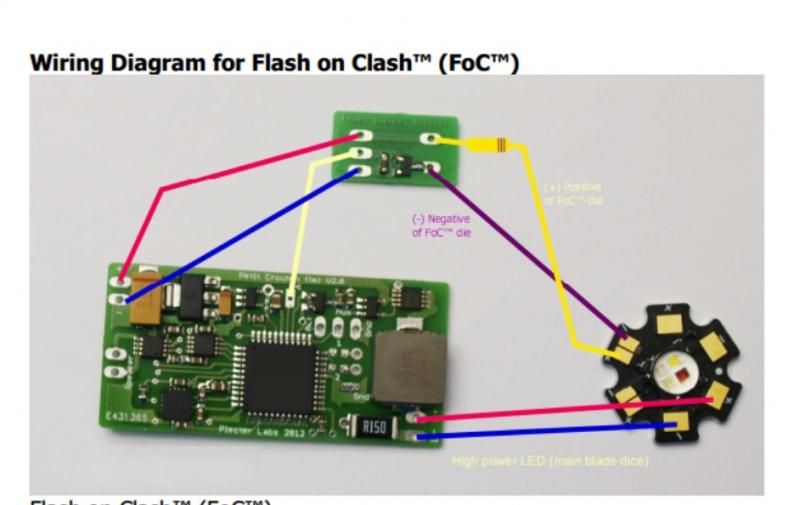
    The plan is to use the white LED as a single flash-on-clash colour, run off the 3.3V FoC pad. Working out the resistor for the single LED is straight-forward, I just need to source a SMD 2512 type resistor 1ohm/at least 2W. Correct?

    I then want to run the two red LEDs in series as the main blade colour (powered using the main high-power LED pads on the PC in conjunction with a 185650 7.4V pack). This is where I'm a little less certain.
    The forward voltage of the red LEDs is 2.4V and they are to be run at 700mA. I understand that, in order to work out the required resistor for a series circuit, I need to add the combined voltage of the two LEDs as my forward voltage in the equation, i.e. 2.4 + 2.4 = 4.8 V.
    So, I have the following formula:
    (7.4V - 4.8V) / 700mA = 3.7142 (or 3.9ohm)

    Is this correct?

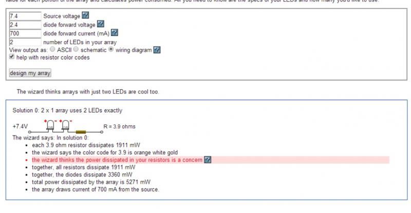
    I also tried the calculator wizard on this and it seems that it presumes my LEDs all have the same forward voltage and adds up the voltages for me. This is what it's telling me ...


    With regards to chosing the appropriate wattage for the resistor, what is important? Is it the power dissipated by the LEDs or the total power dissipated by the LEDs and the resistor?
    It's not that crucial I don't suppose, as I can just use a 3.9ohm / 10W resistor and it will cover it all. But it wouldn't harm to try and understand it for future reference. ("Electronics for Dummies" hasn't arrived yet )

    And, why is the wizard telling me it is concerned about the power disspiated in the resistors? Do I need to worry about that?
    Attached Images Attached Images

  2. #2

    Default

    Well, first off, we need to review a bit of your plans. First off, you can run 2 reds in series off the main pads, without a resistor with no problem. That's how the board was designed to operate.

    The FoC is a different matter. Those should be run off theFoC pad on the bottom of the PC, not the 3.3V pad. For that, you are looking at a 4.7 Ohm, 5W resistor for your needs. The regular resistor for that is chunky, so you may want to invest in a power extender and put your SMD resistor on that. You may want to review the PCv3 manual to go over how the FoC should work.

    Wattage is important in a resistor, because if you pick too low, the resistor can fail, or give off a LOT OF HEAT. Power is dissipated by giving off heat. Fried resistor = fried parts = injured lightsaber user = injured bank account.
    TCSS MODERATOR
    All n00bs READ these first (PLEASE)!!!:
    1. Forum Guidelines
    2. FJK’s “Down and Dirty” guide to Ohm’s Law

    "Yeah, yeah, I've heard it all before... you want blindingly bright, super loud, running 1138 blinkies off of the cheapest sound card you can find AND you want all of it to run on a battery the size of a dime, and run for a very, VERY long time. That one cracks me up every time..."
    My email: fjk_tcss@yahoo.com

  3. #3

    Default

    Quote Originally Posted by Forgetful Jedi Knight View Post
    Well, first off, we need to review a bit of your plans. First off, you can run 2 reds in series off the main pads, without a resistor with no problem. That's how the board was designed to operate.
    Isn't it always safer to use a resistor?

    Quote Originally Posted by Forgetful Jedi Knight View Post
    The FoC is a different matter. Those should be run off theFoC pad on the bottom of the PC, not the 3.3V pad. For that, you are looking at a 4.7 Ohm, 5W resistor for your needs. The regular resistor for that is chunky, so you may want to invest in a power extender and put your SMD resistor on that. You may want to review the PCv3 manual to go over how the FoC should work.
    You're quite right. I did realise I was supposed to use the FoC pad and not one of the accent LED pads (I presume that's what you mean by "the 3.3V pad"). That said, I read this: "FoC? pad is only a 3.3V remote control pad", and misunderstood. I see now that the source voltage from my 7.4V pack is the power source I need to factor in.

    You say I "may want to invest in a power extender and put your SMD resistor on that". I don't understand. The manual states that it already has an integrated Power Xtender. Quote: "(the FoC remote control pad) controls a Power Xtender? that is now under the board, suppressing the need of an external part to drive the FoC die .... The PC also embeds on its PCB the footprint for a 2512 / 2W SMD resistor that suppresses the need of an external power resistor to drive the extra dice."

    I don't understand why I would need to purchase a further Power Xtender.


    Quote Originally Posted by Forgetful Jedi Knight View Post
    Wattage is important in a resistor, because if you pick too low, the resistor can fail, or give off a LOT OF HEAT. Power is dissipated by giving off heat. Fried resistor = fried parts = injured lightsaber user = injured bank account.
    Thank you for your response. Unfortunately, it was rather general and did not address my more specific question. I understand why the wattage of the resistor is important. I'm sure if you review the post, you will see what the more specific question was.
    Last edited by Rich330; 01-20-2014 at 11:02 AM.

  4. #4

    Default

    Quote Originally Posted by Rich330 View Post
    Isn't it always safer to use a resistor?
    Generally, yes. HOWEVER, in this case, since the board controls the current to the LED and automatically reads the LED voltage, it's not necessary.

    Quote Originally Posted by Rich330 View Post
    You say I "may want to invest in a power extender and put your SMD resistor on that". I don't understand. The manual states that it already has an integrated Power Xtender. Quote: "(the FoC remote control pad) controls a Power Xtender? that is now under the board, suppressing the need of an external part to drive the FoC die .... The PC also embeds on its PCB the footprint for a 2512 / 2W SMD resistor that suppresses the need of an external power resistor to drive the extra dice."
    You may want to revisit page 29 in the manual (and the picture under it):

    Pseudo color mixing (without the Color XtenderTM Board)
    It's possible to make an approximate color mixing by using just the on-board PowerExtenders (PEx). Each PEx can drive up to 1.5A with the "direct drive" method, iewithout using any current regulator.
    If the current involved in the additional dice of the blade LED are above 350 mA, anexternal power (2 - 4 W) resistors will be needed, just like when powering a stunt of abattery pack with no electronics. In that case, the 2512 SMD resistor footprint will bebridged and the power resistor placed outside of the board for proper heat sinking.Aside of this, the wiring is the same as a simple (legacy) Flash on ClashTM effect asseen above but generalize to 2 additional channels / dice.


    You will want to run that White at over 350mAh, and you will need and external power resistor (5W), so it's either the chunky resistor I mentioned earlier, or you can get a small power extender and have something to solder a SMD resistor onto, your choice.
    TCSS MODERATOR
    All n00bs READ these first (PLEASE)!!!:
    1. Forum Guidelines
    2. FJK’s “Down and Dirty” guide to Ohm’s Law

    "Yeah, yeah, I've heard it all before... you want blindingly bright, super loud, running 1138 blinkies off of the cheapest sound card you can find AND you want all of it to run on a battery the size of a dime, and run for a very, VERY long time. That one cracks me up every time..."
    My email: fjk_tcss@yahoo.com

  5. #5

    Default

    Many thanks. Very helpful.
    I would never have thought to reference the section on 'pseudo colour mixing' to be honest. I thought I was just setting up a should FoC.
    Time for approach 2, i.e. read the manual from start to finish and get to know the PC inside out, even the sections I don't think relate to my needs.

  6. #6

    Default

    Quote Originally Posted by Rich330 View Post
    Many thanks. Very helpful.
    Time for approach 2, i.e. read the manual from start to finish and get to know the PC inside out, even the sections I don't think relate to my needs.
    That should always be the first thing you do when it's something new to you.
    TCSS MODERATOR
    All n00bs READ these first (PLEASE)!!!:
    1. Forum Guidelines
    2. FJK’s “Down and Dirty” guide to Ohm’s Law

    "Yeah, yeah, I've heard it all before... you want blindingly bright, super loud, running 1138 blinkies off of the cheapest sound card you can find AND you want all of it to run on a battery the size of a dime, and run for a very, VERY long time. That one cracks me up every time..."
    My email: fjk_tcss@yahoo.com

  7. #7

    Default

    Sorry about this, but I feel I have to revisit the FoC solution. FJK, please do not interpret this as me doubting your advice; you obviously know your stuff and your advice is clear and easy to follow.
    However, I have read and re-read pages 28 and 29 several times I am having trouble understanding the logic of the operating manual, i.e. how it applies to my plans. I just want to double/triple/quadruple check that there is no misunderstanding.

    To clarify ...

    - I want FoC using a SINGLE white LED (powered off the FoC pad).
    - I want the two red LEDs to used in series for the main blade colour, running off the "main die onboard driver"

    I referenced the section on page 28 providing instructions for a simple FoC set-up. It provides a specific example of a single white LED running at 1A (i.e. more than 350mA).
    It states that for this set-up the onboard power Xtender should be used in conjunction with the 2512 resistor footprint.

    The section to which you referred me on page 29 is headed "colour mixing" and, whilst the statement on amperage ("If the current involved in the additional dice of the blade LED are above 350 mA, an external power (2 - 4 W) resistors will be needed") is clear, the whole section seems to refer to a set-up featuring two LEDs connected to the FoC pad for a flash on clash with colour mixing. ("additional dice" - plural! .... "generalize to 2 additional channels / dice" plural! and the wiring diagram clearly shows two LEDs connected for FoC).

    Do you understand my confusion?

    If the rule of LEDs running on more than 350mA also applies to a single LED assigned for FoC in exactly the same way, then fine. Just tell me to "shut up, dumb*ss, and do as I say!". Admittedly, in that case I do not understand the example of the 1A white LED in the section "Simple Flash on Clash".
    The solution, and option of an external Power Xtender, which you provided is clear and simple. I'm just seeking 100% reassurance and I hope you can see why I'm uncertain.
    I have committed to making this my future project but I have plenty of time to plan and try and understand it all. I very much appreciate the help.

  8. #8

    Default

    I know exactly what you want to do.

    I showed you page 29 to show you how adding an "external" resistor will work. All FoC it's is lighting up an extra die. Doing it the page 28 way has limitations, remember: "Can do lockup for a max of 10 seconds"? Doing it the way I suggested, would remove that "limitation".

    Of course, you're free to do what you want.
    TCSS MODERATOR
    All n00bs READ these first (PLEASE)!!!:
    1. Forum Guidelines
    2. FJK’s “Down and Dirty” guide to Ohm’s Law

    "Yeah, yeah, I've heard it all before... you want blindingly bright, super loud, running 1138 blinkies off of the cheapest sound card you can find AND you want all of it to run on a battery the size of a dime, and run for a very, VERY long time. That one cracks me up every time..."
    My email: fjk_tcss@yahoo.com

  9. #9

    Default

    Quote Originally Posted by Forgetful Jedi Knight View Post
    I know exactly what you want to do.

    I showed you page 29 to show you how adding an "external" resistor will work. All FoC it's is lighting up an extra die. Doing it the page 28 way has limitations, remember: "Can do lockup for a max of 10 seconds"? Doing it the way I suggested, would remove that "limitation".

    Of course, you're free to do what you want.
    Thank you.

    I understand now that you were showing me an alternative and less restricted solution to the standard solution. Advice going beyond the basics rather than just the "rules". This wasn't originally clear.

    Thank you for your time.

  10. #10

    Default

    I have my PC 3.0 and my extra Power Xtender and I am working on my wiring plans for the FoC part of the circuit.

    The most relevant diagram I can find seems to be this one (below) from the PC 2.0 manual.

    My question is ...

    ... Can I copy this to run my white LED for FoC? I would substitute the resistor in the diagram for the appropriate SMD 2512 resistor (4.7ohm/5W) soldered to the Power Xtender.

    And, trying to understand it all ...
    That way I'm taking the 7.4V supply directly from the power supply pads without the PC's current regulator, so I can run the white LED at 1A. Have I got that right?
    Does having the middle "R" pad on my Power Xtender connected to the FoC pad on the PC cause the white LED to then be activated as FoC only, i.e. it would otherwise be activated constantly?


    As always, many thanks in advance any and all help.

Bookmarks

Posting Permissions

  • You may not post new threads
  • You may not post replies
  • You may not post attachments
  • You may not edit your posts
  •