Page 1 of 3 1 2 3 LastLast
Results 1 to 10 of 22

Thread: Lord Zen's first saber

  1. #1

    Default Lord Zen's first saber

    Hi everyone,
    This is my first post and over the next series of posts I hope to detail a retrospective build log of my first lightsaber.
    Hopefully some people will find these posts interesting or informative.

    The project was completed in early January, but only now do I have the time to do the write-ups.

    Before starting this project I spent a number of weeks reading over the numerous helpful and inspiring posts by the lightsaber building community.
    I am indebted to all those who have taken the time to selflessly share their insight and wisdom with others.
    I am also grateful to those who offer their skills and services to provide the products and technologies that allow our lightsabers to become a reality.

    Over the period of building this saber I learnt much, made mistakes, swore a little, read and re-read guides, burnt my finger once, and became totally engaged in this little project.

    I'm afraid this first post will only be text, but I will include "in-progress" pictures later

    So for now, listed below, is what was included in my shopping order:

    • 1 of: White shouldered 1" thick walled blade tip with reflective disc
    • 1 of: 1" Thick walled Trans White PolyC 40" long (30 inches)
    • 1 of: Collimator Lens 5 deg viewing angle
    • 1 of: LEDengin Lens Holder
    • 1 of: LED Engin LZ4 10W Multi Color (RGBW)
    • 1 of: Star thermal tape pad
    • 1 of: MHS "new style" Heat Sink V2
    • 1 of: 3.7V-14.8V Li-Ion Smart charger
    • 1 of: 2.1mm Power Jack
    • 1 of: 2.1mm Power plug
    • 1 of: Tamiya to JST charger adapter
    • 1 of: Kill plug style 2
    • 1 of: MHS speaker mount V4
    • 1 of: 2w bass speaker
    • 1 of: SPST Momentary tactile switch
    • 1 of: 16mm Anti Vandal Momentary Nickel Plated Switch
    • 1 of: MPS Pommel style 10
    • 1 of: MPS Clip
    • 1 of: MPS Insert style 6
    • 1 of: Screw on LED blade holder style 17
    • 1 of: MHS choke style 2
    • 1 of: Hilt style 3 with standard style switch hole
    • 1 of: 8-32 x 1/8" Set Screw
    • 1 of: Custom Mill Work Fee
    • 1 of: Drill & Tap Hole (8-32)
    • 1 of: Custom Mill Work Fee
    • 1 of: Recharge port hole service (Style 1)
    • 1 of: Machine recessed AV switch hole
    • 1 of: Switch 22 mounting hole service
    • 1 of: 6 Wire quick connector

    • 1 of: PCB for 7.2V Li-ion battery packs

    Some of you may immediately notice a couple of critical things are missing - notably a power source, and a way to regulate the current and voltage to the main LED - but I will get onto these in subsequent posts.

    The aim of the build was to create a simple, sleek, minimalist design - something that could be swung around with a good feel to it
    However, I must admit the copious amount of accent LEDs, while non-canon, were an indulgence.

    To estimate how long I wanted the polycarbonate blade to be I used a broom handle, gripping it in my right hand, my arm relaxed in a natural way against my side and the handle pointed downwards. I then adjusted the location where I gripped the handle until its tip was about an inch off the ground. I then used the measured length of handle between my grip and the tip to determine the blade length. The ordered length needed to take into account where on the saber I would have my forward hand, how much distance would be taken up by the choke and blade holder, and how much blade was countersunk into the blade holder. All this mathematics ended up at a value of 30inches.

    I'm afraid that I am not a machinist, and nor do I have room in my small apartment to house a milling machine and lathe, as much as it would be great to have these. So there are a number of custom work and drilling fees in this order - all of which were delivered exactly as specified. Thanks again to Tim.

    So, that's it for this post - next post, batteries…

  2. #2

    Default Battery pack

    I never intended to build a battery pack


    In fact the whole idea scared the hell out of me - soldering a lithium ion cell was an intimidating prospect.

    I would have much preferred to order a ready made lithium ion pack, but as I live in the old-world the IATA had other ideas - Loose lithium ion packs cannot be shipped by airfreight now, and with the recent incidents with the Boeing 787 this is understandable.

    I liked the idea of using 14650 batteries as they have a small diameter, and placed side-by-side in a hilt still have room above them to seat electronics. Being slightly longer than the 14500s (65mm vs 50mm) they offer a little more run time due to the larger milliamp hours (mAh) rating.

    Knowing that Lithium-ion was going to be the only way to provide the voltage and amp hours I wanted I needed to source a set of 14650s, which ended up with me ordering some protected lithium-ions batteries from eBay, imported from China. The old-world apparently doesn't do 14650s

    With the batteries on a slow boat from the near other side of the planet, I had plenty of time to read Azmaria Dei's guide to Lithium Ion Battery packs - and prepare.
    I read this post, re-read it, and then read it some more for good measure.


    Now, I would not recommend anyone consider the following advice or guidance - this is simply what I did

    When the batteries arrived I knew that they were protected cells and would need to be de-protecting. I intended to connect the cells in series to deliver 7.2V so this would need a 7.2V protection circuit, and using two, competing protection circuits would not be a good idea.

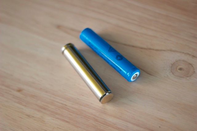
    To remove the protection circuit I had to unwrap the cells from their blue plastic wrapping case. You can see the bare-metal cell in the picture below, the protection circuit is on the -ve terminal with a metal connection running along the other end.


    You might also be able to see the thin piece of yellow cellophane plastic that isolates the metal connection for the cell casement - it is very important the metal case does not touch this metal connection. I carefully cut this long metal tab, lifted the protection circuit from the negative and cut the join to the negative terminal. I then used 14mm heat shrink to re-wrap the individual metal cases and used the metal tabs to solder the cells together along with the 7.2V protection circuit.


    With much trepidation I tested my homemade battery pack.
    I hooked up the pack to the charger using a JST connector and gingerly turned on the power.
    A new battery pack needs to be hooked up to a charger to enable the protection circuit, otherwise the pack remains in a dormant state and no power can be drawn from it.

    I was happy that the charger showed red - indicating the pack was at least charging.
    I was then really happy when I disconnected the charger and measured 7.2V from the pack.
    I then left the pack charing for about 20mins, paranoid that the pack would go bang.

    Fortunately there were no fireballs, and the charger LED showed green, indicating the pack was fully charged.

    It looked like my homemade lithium ion pack was a success
    Last edited by Lord Zen; 05-26-2013 at 01:56 PM.

  3. #3

    Default The LED Engin...

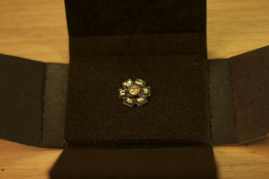
    This is the LED Engin, and sadly it is not the originally ordered one


    Because I could not decide on which colour I would like my saber blade to be, I elected to use a multi-coloured RGBW LED and originally considered using potentiometers to adjust the current level to adjust the colour.

    Fortunately a couple of products were announced at this time that offered RGB colour mixing on the soundcard. My decision was to go with Naigon's Igniter soundcard - I appreciate that this product is not sold in this store, so will not go into details.


    The LED Engin had many names during the soldering process - none of them repeatable in this forum...

    This LED was the hardest thing to solder on the project by a long way, but thanks to Fender's wiring guide I was at least prepared for this.


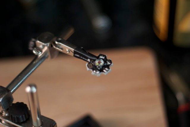
    I used a 30W soldering iron and the LED star was held in place using a helping-hands grip system. The aluminium base of the star does an incredible job of dissipating heat, so you need to work fast. I also found out that the LED Engin is more tolerant and robust to heat than I initially thought.


    Once I thought I had finished soldering up this beast, and to my horror, I broke one of the pads on the green die. The copper pad lifted off the star and the small track to the die snapped.
    As I had decided to use the LED Engin specifically for its colour mixing I was just a little upset - so I decided to try to recover this set back.

    Using a little sanding I filled back the coating on top of the copper track and attempted to solder to it. This worked temporarily - but was too delicate to handle any wire movement. Knowing the piece was useless to me I practically covered the area in solder - but to no avail. I did however learn how robust these things are - all the other dies still work, and so this broken LED has been consigned to my box of spare things. The red and blue still work - and that makes purple

    So, having learnt my lessons from the first LED and improved my soldering skills, I ordered another. I also moved to solid core for the connections, with the intension of using strand-core beyond the heat sink. I found this made the soldering easier for me.

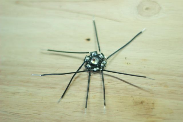
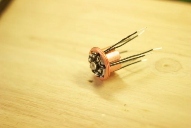
    Below you can see all the pads wired up - all colour coded black to make things a little more trickier:


    And with the LED Engin mounted on the heat sink with the star thermal tape pad and the wires threaded through waiting for connection to coloured multi strand wire. I use a screwdriver to push where the star pad overlaps into the heat sink holes:


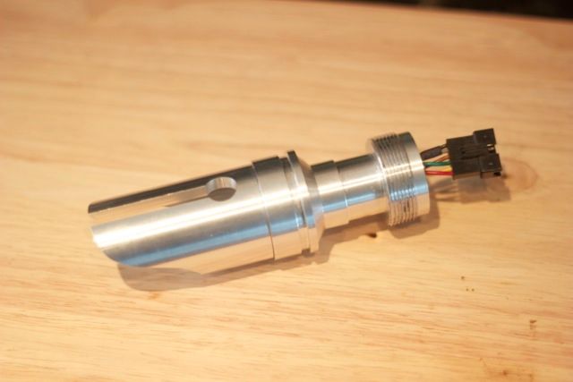
    Finally the LED housed, with its lens and holder, wired up with the 6 wire quick connector and held in place in the customised blade holder 17 by the choke section:


    The blade holder customisation simply has a 6mm wide cut made into it with a 12mm diameter hole at the end. The blade holder screw is underneath, directly opposite the 12mm hole.

  4. #4

    Default

    Quote Originally Posted by Lord Zen View Post
    The LED Engin had many names during the soldering process - none of them repeatable in this forum...


    Below you can see all the pads wired up - all colour coded black to make things a little more trickier:
    I found these two statements to be quite amusing. The first one I can relate to personally. The second...well, it just boggles my mind
    We all have to start somewhere. The journey is all the more impressive by our humble beginnings.

    http://led.linear1.org/1led.wiz for the lazy man's resistor calculator!
    http://forums.thecustomsabershop.com...e-to-Ohm-s-Law for getting resistor values the right way!

  5. #5

    Default

    Unfortunately, on the day I visited my local electronics store their approach to solid core wire was much like Henry Ford's - any colour you wanted as long as it was black

    Granted it was a stock availability issue at the time, but there was no time for such nonsense - I had a lightsaber to build!

  6. #6

    Default Powder coating...

    I lament not asking Tim to do powder coating on the main hilt.


    But to be fair, I didn't realise until I received my order how much better it would look accented with matt black. But more wisdom learnt - let the experts do the powder coating..

    I did manage to find a local powder coating who would do small jobs. They would normally do bike frames so I hoped they would be willing to coat the saber hilt.

    After getting past the perplexed look of the powder coat guy when I showed him the saber hilt, and pointing out the intricacies of the work that was required, he said that they could do the work but the masking work would be labour intensive and expensive. They could do it for a stupid amount of money, or I could go away and do it myself.

    So this is when I learnt the time consuming experience of masking.
    I purchased some special masking tape, that could handle the baking temperatures of powder coating, and set about my work. As I wanted to have the groves in the hilt black I needed to mask pretty much everything and carefully cut the edge of the tape with a scalpel to reveal only the groves. The various holes within the hilt, including each end of the tube also needed to be blocked with bungs. It was during this process that I suspected powder coating the whole of the hilt black and taking the top layer of paint off using a lathe might have been the easier way. But with no lathe available, this wasn't an option. The whole task took about 4 hours to complete.

    I was really proud of my fully masked hilt, with all the groves and details neatly cut in, it seemed a shame that I would soon be removing it all again.

    The fully masked hilt was then powder coated, and the guy charged me about £5 to do so.

    Next came the arduous task of removing all the masking tape, and as the paint had dried hard it was a painful experience removing the tape with my fingernail, as I didn't want to damage the aluminium finish underneath.
    In some places taking the masking tape off also chipped a little of the powder coating at the edges so I needed to touch them up with some matt black enamel paint.

    Fortunately I don't have any photos of this whole shameful process

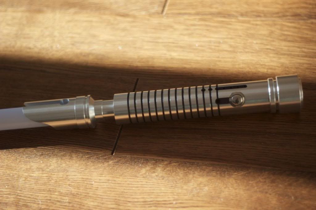
    However, below is the powder coated hilt, with attached pommel, choke and blade emitter, all basking in the sun:


    There are no electronics in here yet and I just rested the Anti-Vandal switch in its hole.
    Along the top you can see the where the 7, yes seven, accent LEDs will go - I think I admitted that these were a bit of an indulgence
    Two LEDs will be located separately in the little black spots in the grooves, and the remaining 5 will be spaced equally along the black strip to the right.

    Tim did an incredible job on all the drilling and milling work this required - and I think it looks fantastic.

  7. #7

    Default

    I'm loving the custom bladeholder.

    I'm glad to hear you're learning a lot. You're definitely doing a few things the hard way. In the future, if you just want to color in the grooves, you could just use spray paint. Durability is less of an issue in recessed areas. You don't even need to mask the hilt, just take a sanding block and remove the upper material and it's done. Now if the color scheme were reversed and you wanted the grooves clean and the main section black, then the PC would be an ideal choice.

    Your way is fine, but it's a lot more effort. As I'm sure you've learned

    I'm looking forward to seeing all those accent LEDs wired up.
    We all have to start somewhere. The journey is all the more impressive by our humble beginnings.

    http://led.linear1.org/1led.wiz for the lazy man's resistor calculator!
    http://forums.thecustomsabershop.com...e-to-Ohm-s-Law for getting resistor values the right way!

  8. #8

    Default Accent LEDs

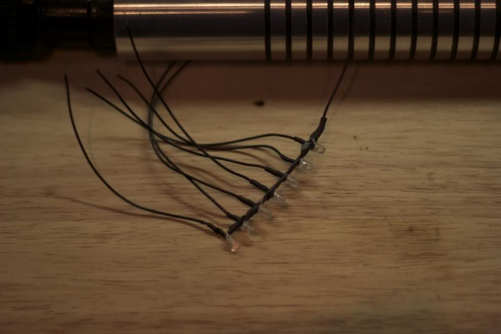
    To give the saber some bling I decided that I would use nearly all of the accent LEDs that the Igniter soundcard can provide.

    I know none of the movies have flashing LEDs all over the place, but having one or two is useful - just for debugging and reminding you that you've left your lightsaber on.
    So of course having seven would be even better.

    I used a chain of 3mm (T3), crystal clear LEDs, which would mean that they would be transparent when powered off, and not detract from the saber's simple design.
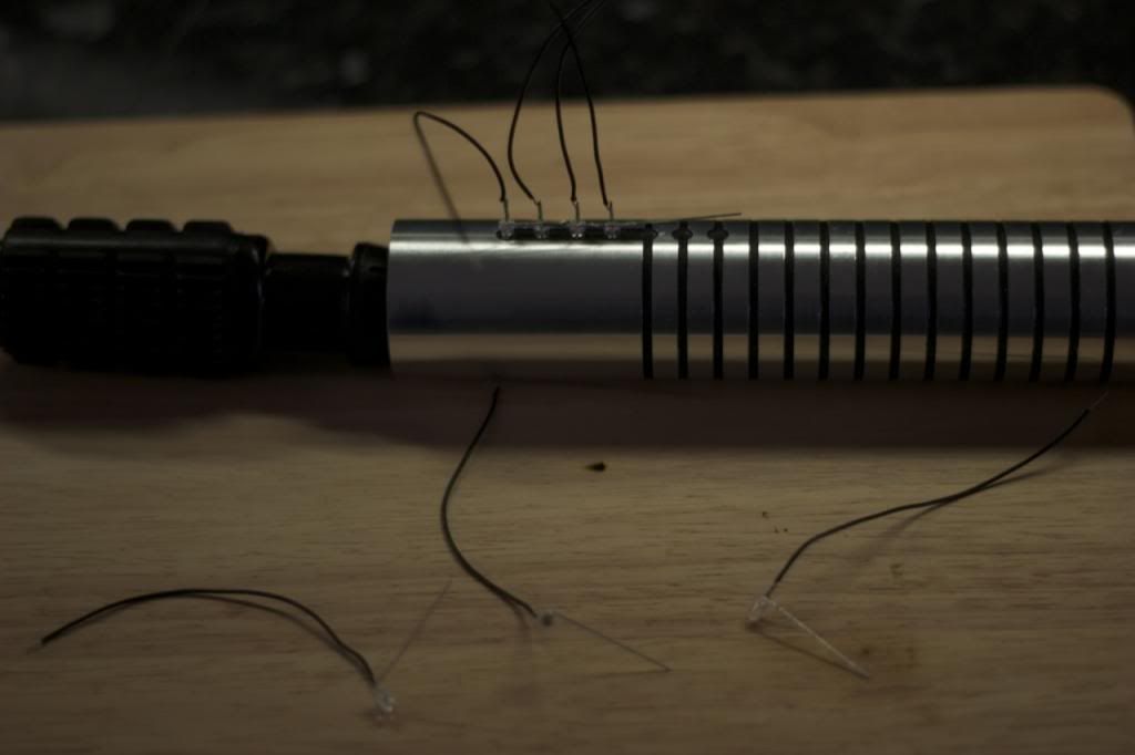
    I carefully bent all the Anode legs of the LEDs to 90 degrees so I could solder them together in a chain.


    I pushed each LED in turn into the holes cut into the hilt to make sure that the spacing between them would be correct. The anodes were soldered together and any overlap was trimmed. After the powdercoating and sanding the holes a little the LEDs are quite a friction fit into the hilt, so I had to be careful not to get any of them stuck.


    Once the chain was completed, I added a little heat shrink to the ends to cover up the solder joins and exposed LED legs. I then wrapped electrical tape around the linked LEDs, again to protect against exposed connections.

    What isn't apparent when the LEDs are powered off are their colours. I decided to avoid a chromatic look, and picked a more random ordering.

  9. #9

    Default

    so the accent LEDs are different colors, a mix of colors?
    When I picture that in mind mind, it looks awesome!!
    Sounds like it'll give it a nice retro Sci-fi look. You know, back when everything had flashing lights and such, oh yeah, like in Star Wars.
    Cant wait to see the finished saber.
    ~ The Yin ~

    “Yeah I’m pack’n heat! It’s to prevent anyone from making me cold

    For the saber building Younglings and Padawans: Basic Saber Building and The Saber Building Dictionary!

  10. #10

    Default

    Quote Originally Posted by The Yin View Post
    so the accent LEDs are different colors, a mix of colors?
    Yeap, I arranged them Blue, Green, Orange, Blue, Yellow, Green, White - and this decision took longer than it should. It is surprisingly difficult to do "random"

    I was going to have a purple in there, but it just wasn't as bright as the colours. It almost looked like the purple was broken or mis-wired compared to the other LEDs - so I dropped it and replaced it with the white.


    Quote Originally Posted by The Yin View Post
    back when everything had flashing lights and such, oh yeah, like in Star Wars.

Bookmarks

Posting Permissions

  • You may not post new threads
  • You may not post replies
  • You may not post attachments
  • You may not edit your posts
  •