Yes. You'll want a latching switch for that, or else you end up with a dead-man's switch that you have to hold in to keep the saber on.


Yes. You'll want a latching switch for that, or else you end up with a dead-man's switch that you have to hold in to keep the saber on.
We all have to start somewhere. The journey is all the more impressive by our humble beginnings.
http://led.linear1.org/1led.wiz for the lazy man's resistor calculator!
http://forums.thecustomsabershop.com...e-to-Ohm-s-Law for getting resistor values the right way!

thanks, referencing the wiring diagram on first page will the foc being directly tied to the battery affect the latching switch
Olc-Pa Mabec
I'd move the FoC lines to the recharge port instead of directly tying them to the battery. Then the kill key will kill everything, including the FoC wires.
We all have to start somewhere. The journey is all the more impressive by our humble beginnings.
http://led.linear1.org/1led.wiz for the lazy man's resistor calculator!
http://forums.thecustomsabershop.com...e-to-Ohm-s-Law for getting resistor values the right way!
Good Call/ Shouldn't be to hard I will draw A new wiring diagram tonight to put on here. One last question. I am putting a crystal chamber in will it be possible to add a second Accent LED? I already have two accents in my switches and one extra accent on the exterior/ this completely covers all Accent LED slots. can I throw an extra one on there?
Olc-Pa Mabec
Olc-Pa Mabec
Yes. You can easily wire it in as a Progressive Power On LED (see p.18 of the PC2.0 manual) and then the crystal chamber will actually mimic the blade effects.Originally Posted by patolcott

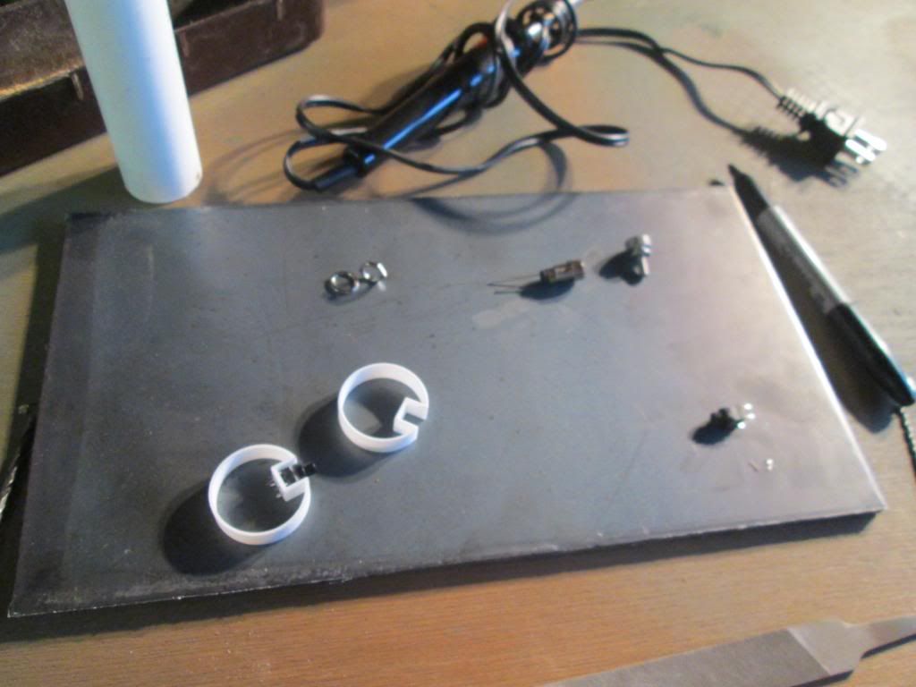
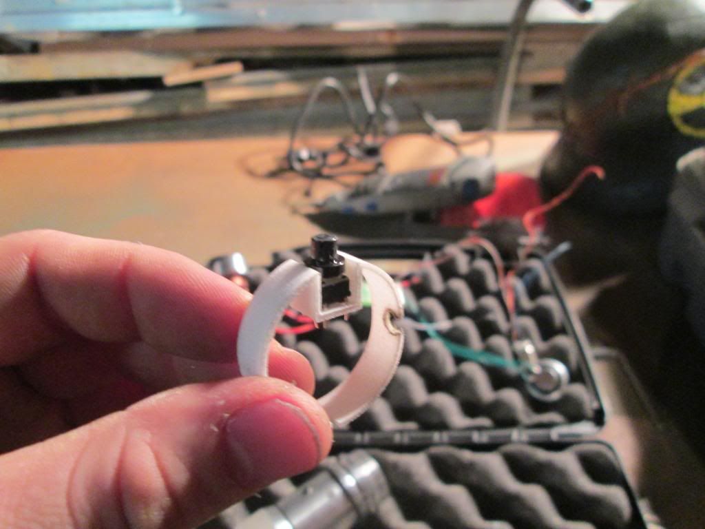
I love the PVC switch rings in your pics. Did you make those yourself, or are they 3d printed, or something else?
We all have to start somewhere. The journey is all the more impressive by our humble beginnings.
http://led.linear1.org/1led.wiz for the lazy man's resistor calculator!
http://forums.thecustomsabershop.com...e-to-Ohm-s-Law for getting resistor values the right way!
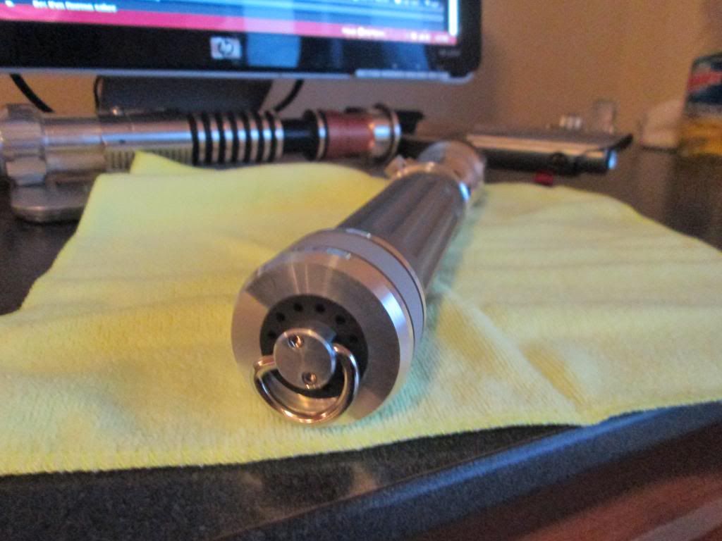
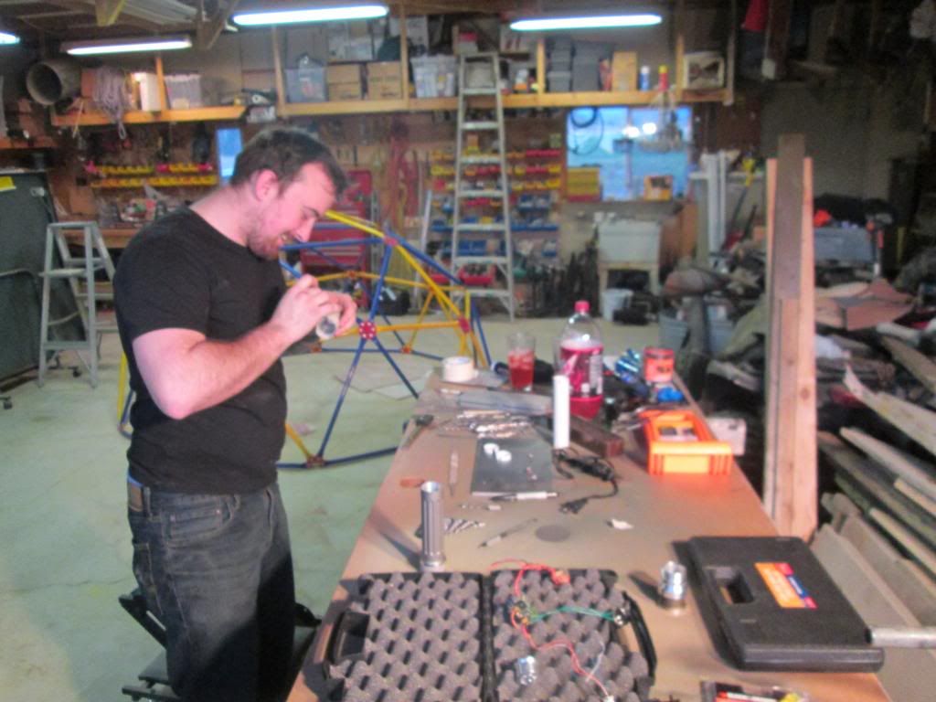
Wow, a little disappointed to see that you're assembling this in some sort of workshop and not in a dark cave somewhere....
That said, good to see it coming together now!
The lightsaber hilt is capable of producing a blade of pure energy. The lightsaber hilt has proven to be completely safe. The saber blade however has not. Do not touch the operational end of the saber blade. Do not look directly at the operational end of the saber blade. Do not immerse the saber blade into your flesh, not even partially.
@Silver serpent, they are 3d printed, I did not print them though, I just discovered 3d printing myself otherwise i would have. I know we are not supposed to solicit here but i will say to go to fx sabers>the outer rim> force relics and you will find what you need. I suggest 3d printing them yourself though it is cheaper and faster because they ship from england I believe. Oh and lastly I do not have a PC 2.0 I have the 1.5 can I still do the progressive power on thing? that sounds awesome.
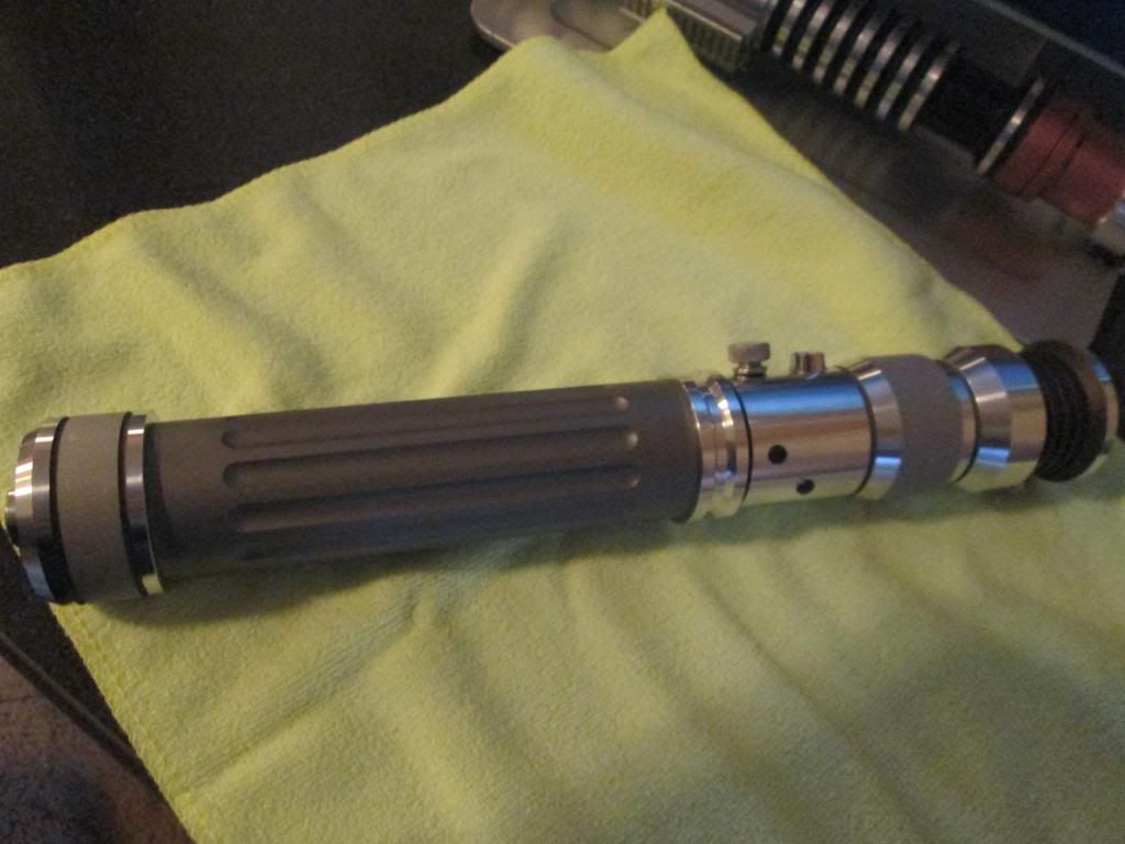
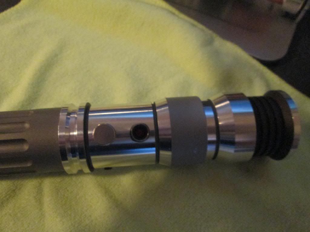
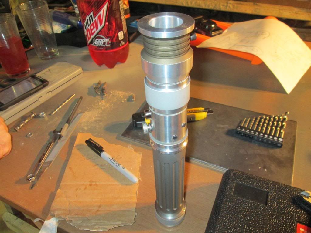
@kevin Starwater, your telling me man With all of the waiting for parts it is so good to finally be getting things all together now. Now all I have to wait for is my 3d print of my chassis to come in. it ships on the 22ndcant wait!
Olc-Pa Mabec
You can do it with the 1.5 as well. You wire the pos(+) of your accent to the pos(+) pad of the main LED, and then run the neg(-) of your accent LED to the neg(-) power input on the board. It's on p.15 of the PC1.5 manual. The procedure is the same, no matter which version of the board you are using. You will need to use a resistor, and the source voltage will be equal to the Vf of your main LED. The formula for calculating the resistor is in the PC manual, or you can just use an online resistor calculator.
We all have to start somewhere. The journey is all the more impressive by our humble beginnings.
http://led.linear1.org/1led.wiz for the lazy man's resistor calculator!
http://forums.thecustomsabershop.com...e-to-Ohm-s-Law for getting resistor values the right way!
Thanks silver! I actually went back over the 1.6 manual and I found what you are talking about on page 14 thanks for the extra input. I will be doing a wiring test this weekend to if everything works... Fingers crossed.
Olc-Pa Mabec
 Posting Permissions


 Reply With Quote
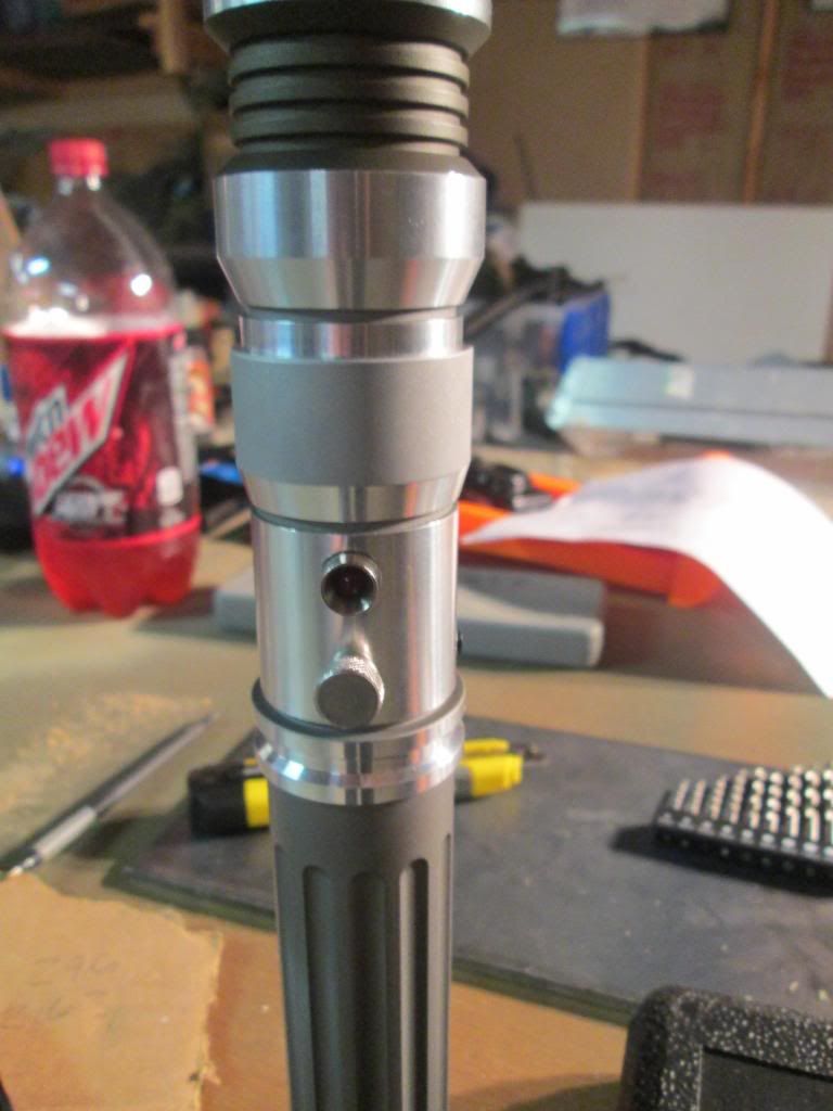
Bookmarks