Page 1 of 2 1 2 LastLast
Results 1 to 10 of 11

Thread: '05 Vader quick disconnect wiring

  1. #1

    Default '05 Vader quick disconnect wiring

    OK so my conversion parts for my 2005 Vader arrived several days ago and I have taken my saber apart. I want to start wiring but according to the conversion post I have the quick disconnect. However, the post only shows how to wire a normal '05 Vader. I have an idea on how the wiring should go but I don't want to proceed for fear of mucking this up. Before anyone flames me for posting this I have looked everywhere and searched with every keyword I could think of and have not found anything on this. I just looked for about the fifth time today before posting this. I did find one post with a few pictures and a brief description of the wiring here but I'm really new at this and it helped very little. I need like a step by step with diagrams. I feel kinda dumb. Someone please help.
    Last edited by DarthJim; 08-12-2012 at 11:41 AM.

  2. #2

    Default

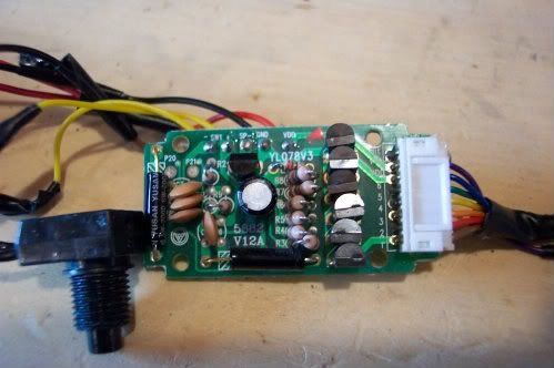
    The wiring on your DIN plug equipped board should be identical to the wiring on the other style board. what exactly do you need help on? does you board look like this;

    Got a question? Start Here. Have you tried the Thread Index yet? Most questions can be answered there.

  3. #3

    Default

    Honestly I have no clue what the board looks like. It's still sitting in the black tube that connects to the battery pack. I don't want to break the thing apart cuz I'm assuming I need it. I just wanna know how/ if the wiring for the LED differs from what is shown on the conversion page. I was thinking of disconnecting the wires on the shock sensor from the LED with everything connected like here. However that leaves me with only the purple wire to connect to the positive while everything else would be connected to the negative...if my thinking is correct that is. The blue and gray wires mentioned in the tutorial aren't on my connection. I'm assuming this is because the shock sensor is directly attached to where the wires are. This is shown here Also here is a picture of everything disconnected for reference. If my ideas for wiring are correct then please let me know. If not then please can you detail how I would go about the wiring otherwise.

  4. #4

    Default

    Unfortunately you will have to open up the plastic casing to get to the board, it cracks apart at the seams, and will go back togather w/ some masking tape. it will be easier to know what your wrking w/ then cutting wires a guessing.
    "A foolish man fights a fight he'll lose, and lose foolishly".

  5. #5

    Default

    So after much effort and swearing I finally broke my board out of it's casing. And whadda know it looks just like the picture above. Now the post I noted above does detail how to rewire everything but my skills at this are limited at best and I really don't wanna do all that. If I have to I will but I'm gonna need some major help in the form of a completely detailed tutorial with pictures. I really don't wanna be a huge pain in the rear so my initial question remains: Is there a way I can the leave the whole connection as is and just disconnect the wires from the LED strip then connect everything as in the Vader tutorial and leaving the shock connection as is. Here's a diagram to explain:
    Last edited by DarthJim; 08-13-2012 at 08:05 AM.

  6. #6

    Default

    It would be nice it it would work that way, but unfortunately the kit doesn't allow for the stock disconnect plug. The led fits in the kit (the new aluminum blade socket), and the kit takes up all of the space in the hilt where that stock QD was. The conversion from the point you're at now is identical to the tutorial already posted. The only part from the original saber you'll be re-using is the black plastic housing the sound board is contained in, the shock sensor (which will have to be de-soldered from the DIN plug and re-soldered to the board, either the way it was shown in the other topic, or by adding wires to it) and the main blade plug-in harness (the white one that plugs directly to the board). The led strip, the stock DIN plug, and those other plastic parts the blade used to be held in place with are not re-used.

    There may be other members on the forum that have pictures of this type of Vader saber, so maybe they will post them for you.
    Last edited by Jay-gon Jinn; 08-13-2012 at 09:04 AM.

    Got a question? Start Here. Have you tried the Thread Index yet? Most questions can be answered there.

  7. #7

    Default

    So you're saying that if it wasn't so damn big it would work? Well that's just my luck. I'm not even sure I have a solder sucker anywhere ant I know solder wick is really pricey. Also there's a metric butt ton of glue where the shock sensor so hopefully I can get at it. I might still try to see f I can fit everything down in there if I take all the plastic white stuff off. If not can you show me a diagram of how to connect the clash sensor w/ wires?

  8. #8

    Default

    I think I still have that connector in a parts bin somewhere, and if so, I might be able to do a mini tutorial on how to do it...it will be the way I would do it, which is not to say it would be the only or best way to do it.

    Got a question? Start Here. Have you tried the Thread Index yet? Most questions can be answered there.

  9. #9

    Default

    OK great thanks. Now if I were to do it as in my diagram is the wiring correct? I just put everything together and crammed it in there and it looks like it'll fit. Haven't tested any connections yet because I cut the switch wires too short so I have to desolder those and put new longer ones on...Guess I'm doing some desoldering anyway...*sigh*

  10. #10

    Default

    ok so I've got a small problem...well two. first my board is slightly different than yours. under the 'hit' spot on my board there's one that says vcc. I tried to connect the clash sensor to both and nothing no clash sound. what did I do wrong? Also I accidentally ripped the wires off of the white thing on brown circle that links to the battery pack. Can I just remove the white piece and directly solder the wires. I see in the pictures you have in the other post that those wires don't seem to be connected to anything so I'm assuming that's what you did

Bookmarks

Posting Permissions

  • You may not post new threads
  • You may not post replies
  • You may not post attachments
  • You may not edit your posts
  •