Page 7 of 9 FirstFirst ... 5 6 7 8 9 LastLast
Results 61 to 70 of 86

Thread: Sound problem on 2011 Ultimate FX sound card

  1. #61

    Default

    Well, I believe there is a main problem here,
    Jvidamins is using an Ultimate FX board, not one of the "old-style" Hasbro econo-boards.
    The board has one negative and 5 positive pads, used to drive the 5 led-ladder sections.
    With this setup I think the PNP doesn't work, probably an NPN will be required.
    My plan would be to use an NPN transistor (a TIP41 for example) wiring it this way:

    - Base to LED1 pad
    - Emitter to ground
    - Collector to LED negative
    - LED positive to +Vbatt (through appropriate resistor if needed)

    This week I have to modify one of these boards to drive an RGB for a friend.
    If interested, once I complete my tests I can post the results.

    However, I believe this specific discussion should be moved to the Ultimate FX board thread.

  2. #62

    Default

    Quote Originally Posted by Don Se Wion View Post
    Well, I believe there is a main problem here,
    Jvidamins is using an Ultimate FX board, not one of the "old-style" Hasbro econo-boards.
    The board has one negative and 5 positive pads, used to drive the 5 led-ladder sections.
    With this setup I think the PNP doesn't work, probably an NPN will be required.
    My plan would be to use an NPN transistor (a TIP41 for example) wiring it this way:

    - Base to LED1 pad
    - Emitter to ground
    - Collector to LED negative
    - LED positive to +Vbatt (through appropriate resistor if needed)

    This week I have to modify one of these boards to drive an RGB for a friend.
    If interested, once I complete my tests I can post the results.

    However, I believe this specific discussion should be moved to the Ultimate FX board thread.
    Definitely interested in your results. Let me know. If I get time I'll also try out the NPN transistor and see if that works. Also, what thread are you talking about? I think this thread is the biggest one so far on these boards. Maybe I missed it. There's one on this vs the 2010 version. I'll definitely post my final findings from here to there.

  3. #63

    Default

    Well I got a TIP 31 NPN from the Shack and wired like you say above. It turns on with sound and light for a couple seconds, but then shuts off abruptly as if something's shorting out??? Any ideas?

  4. #64
    Council Member
    Jedi Council Member
    Rhyen Skytracker's Avatar
    Join Date
    Feb 2009
    Location
    Covington, GA
    Posts
    2,550

    Default

    Did you wire the base of the transistor to one of the board LED + ?

    I plan on wiring another one with this set up this weekend and will post pics and videos.

    Live long and...I mean May the force be with you. http://saberconcepts.50.forumer.com/index.php

  5. #65

    Default

    Quote Originally Posted by Rhyen Skytracker View Post
    Did you wire the base of the transistor to one of the board LED + ?

    I plan on wiring another one with this set up this weekend and will post pics and videos.
    I wired it to all 5 of the board LED +'s. I have them bridged, so I couldn't just connect one. Is that my problem, or is it ok to connect all 5?

  6. #66

    Default

    Quote Originally Posted by jvidamins View Post
    Definitely interested in your results. Let me know. If I get time I'll also try out the NPN transistor and see if that works. Also, what thread are you talking about? I think this thread is the biggest one so far on these boards. Maybe I missed it. There's one on this vs the 2010 version. I'll definitely post my final findings from here to there.
    Sorry, I was really convinced this thread was part of the 2010 board discussion, my mistake.

    Anyway, I will try to find some time to test the wiring tonight before heading for the pool and hopefully post the results tomorrow morning.

    I would also suggest wiring the base to only one of the LED+ pads, I fear 5 pads may be overdriving the base of the TIP41.
    Best best choice would be LED1 so the blade will turn on at the beginning of the ignition sound and turn off at the end of the shutdown sound.
    At least this is the general setup I use when "upgrading" MR boards.

    **** Update !!!

    Before you make a bad mistake like me I have to warn that my theory proved wrong.
    Wiring the transistor base to one of the LED+ pads burned the SMD transistor on the sound board, and that's probably what happened to Jvidamins as well.

    After some more attempts I managed to get the board working replacing one of the SMD transistors with TIP42C.
    I took some pictures of the working board and will post them tomorrow to show my setup.

    The max current I got with this solution was about 1600mA wiring blue and red from a Cree RGBW (without resistors)
    Last edited by Don Se Wion; 01-24-2012 at 12:26 PM.

  7. #67

    Default

    I know I'm going to break a forum rule here by double posting, but I think in this case it could be acceptable because this is going to be a mini tutorial and I just want to keep it clean and simple instead of attaching it to my previous post since it may cause confusion. If the mods won't agree with my point of view I can merge the two posts. All pictures are clickable.

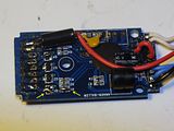
    First step in my customization is to remove transistor Q1 and its driving resistor R1 and create two jumpers.
    Removing resistor R1 will help sending the TIP42C in staturation state, increasing the mA output; leaving the resistor in place will give less mA to the LED.

    In the picture I used arrows to mark the two jumpers I made between the pads in order to bring the signal to the TIP42C base through LED1 pad. If you have troubles creating the jumpers with solder only, you can use a short wire as a bridge.


    As you can see from the picture, I also removed transistor Q4 because I'm going to use LED4 pad to hold the TIP42C emitter; this is not strictly necessary if you plan to wire the transistor on-the-fly instead of securing it to the board (no jumpers needed here).

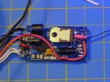
    Before you ask, I moved both capacitor and PTC to the top side of the board to have a flat base that will help me with the installation; again, this is not striclty required, I just like it this way.

    Next step is to solder the TIP42C to the board.
    If you are planning to wire the transistor on-the-fly make sure to connect it in a similar way.

    As said before, I'm going to use the following pads:

    - Base --> LED1
    - Emitter --> LED4
    - Collector --> normally I coil the collector leg to help soldering the wire going to the LED

    You may need to enlarge the pad holes to fit the transistor legs, I think I used a 1mm drill bit here.


    The short red wire you see in the bottom right corner is bringing the B+ voltage directly to the emitter.
    Initially I relied to the Q4 track on the board but I was getting less mA to the LED.

    The job is now complete and we can move to the real tests.
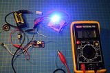
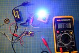
    As power supply I used 4 NiMh AA batteries (4.8V) and the LED is a Cree RGBW.
    The LED+ is wired to the collector and the LED- directly to the battery negative.

    1st test - Blue die with 1 Ohm resistor ---> 720 mA


    2nd test - Blue die, no resistor ---> 1160 mA


    3rd test - Blue and Green dies, no resistors ---> 1330 mA


    4th test, Blue and Red, no resistors ---> 1610 mA


    As you can see, the mA rate given to the LED depends mainly on the type of LED and batteries you are using.
    Probably using 4 alcaline batteriews (6V) you can get more mA, but you will definitely need to use resistors.

    Last consideration is that if you are planning to use an LED with a single die you can definitely skip this mod and wire the 5 LED+ pads directly to the LED.
    If you plan to use multi-die LEDs or RGBW, then you may consider this solution to feed more current to them and avoid burning the tiny SMD transistors on the board.

  8. #68

    Default

    Thanks for such a great post! In fact, this should be moved to its own thread so people can find it. Anyway, I do have a couple questions. First off, you are using an NPN transistor right? And can I use a TIP31 NPN, because that's all the Shack had? Also, your last comment made it seem like this mod is not for me since I'm only using a P4 green LED. I'm only getting around 700 mA's wiring directly from the board to be LED, so I really need to use a transistor to get more juice to my LED. As I am very inexperienced with electronics, please let me know what you think I should do with my setup to get it working good. Thanks!

  9. #69

    Default

    Well, first thing I would try is to check if you have any fried transistor on the board after the tests.
    Just wire everything up without LED and transistor and measure the voltage between the LED+ and LED- pads.
    If the voltage is 0 when the board is off everything should work fine; when active the output voltage should get near battery voltage.

    In my case, with a fried transistor I was getting around 2.3V with the board turned off.
    I saw the same behavior with a Yoda Force FX with 3 fried transistors (not my fault there ) and the boards are pretty similar in design in the LED driving section; I did a similar mod with the Yoda board and it's working like a charm again.

    If you discover that one (or more) transistor is fried, you can replace the board again or try with my modification.
    Just make sure to use a PNP transistor like the TIP42 (or equivalents) because we need to be consistent when replacing the transistors on the board which are PNP.

    Regarding the main issue with lower current output I would suggest two things.

    First, I would wire the P4 negative directly to the battery negative.
    Sometimes the tracks on the boards are simply not designed to carry high currents.

    Second, considering that you are using a single 18650 lithium battery providing 3,7V, I would wire the P4 without resistor.
    The max forward voltage accepted by the P4 green is 4.1V, so with 3.7V should be definitely safe to discard the resistor.
    To check the P4 specs you can download the datasheet here.

  10. #70

    Default

    Quote Originally Posted by Don Se Wion View Post
    Well, first thing I would try is to check if you have any fried transistor on the board after the tests.
    Just wire everything up without LED and transistor and measure the voltage between the LED+ and LED- pads.
    If the voltage is 0 when the board is off everything should work fine; when active the output voltage should get near battery voltage.

    In my case, with a fried transistor I was getting around 2.3V with the board turned off.
    I saw the same behavior with a Yoda Force FX with 3 fried transistors (not my fault there ) and the boards are pretty similar in design in the LED driving section; I did a similar mod with the Yoda board and it's working like a charm again.

    If you discover that one (or more) transistor is fried, you can replace the board again or try with my modification.
    Just make sure to use a PNP transistor like the TIP42 (or equivalents) because we need to be consistent when replacing the transistors on the board which are PNP.

    Regarding the main issue with lower current output I would suggest two things.

    First, I would wire the P4 negative directly to the battery negative.
    Sometimes the tracks on the boards are simply not designed to carry high currents.

    Second, considering that you are using a single 18650 lithium battery providing 3,7V, I would wire the P4 without resistor.
    The max forward voltage accepted by the P4 green is 4.1V, so with 3.7V should be definitely safe to discard the resistor.
    To check the P4 specs you can download the datasheet here.
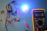
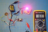
    Ok, I tried what you suggested. With my LED+ (all five connected via bridge) and LED- connected directly to my multi-meter, I'm getting around 82mV with it off. With it on, I'm getting 4.17V. Can I assume then that I do not have a fried board transistor?

    Also, I tried wiring it up with no NPN or PNP transistor but connecting the P4 negative directly to the battery negative and I got .78mA, vs .74mA without doing that. So, it made a little difference, but not much. I'd REALLY like to get to 1200mA, like I did with my 2010 econo board using a TIP42 PNP transistor. I've tried 2 different TIP 42's and neither of them will allow the saber to turn on. What should I do now?

    Oh ya, I've never used a resistor with this configuration, as the board can handle 5-6V I've read, and I'm only using the one 18650. Or are you talking about removing one of the board resistors???
    Last edited by jvidamins; 01-26-2012 at 01:04 PM.

Tags for this Thread

Bookmarks

Posting Permissions

  • You may not post new threads
  • You may not post replies
  • You may not post attachments
  • You may not edit your posts
  •