-
-
Jedi Initiate


I've read through your other post, trying to follow your build intent. Looking at your list, I've got some questions/problems/issues (in no particular order):
1.) The Hasbro Obi-wan uses a momentary switch. I know you would have found that out before you ordered through reading, and just haven't edited your post...
2.) Your battery solution w/ the (2) 14500's and pcb w/ recharge jack implies you're making a pack, but I don't think you need the 2AA holder with that. Just encase the batteries and pcb in heat shrink...
3.) Use the 8.7 degree lens with the rebel star...
4.) I think you want the 2.1mm plug adapter for the smart charger. Don't forget to order the charger...
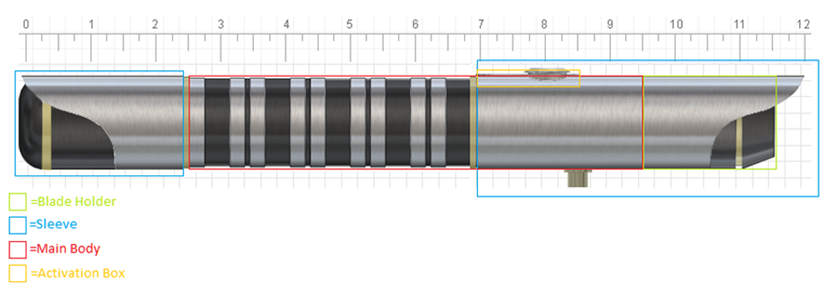
5.) The trim rings extend out beyond the OD of the main body and lock between thread sections unless you modify them, but your shroud at the pommel end laps over the ring. Were you going to modify the ring (i..e. cut part of it off) to allow that to happen?
6.) You need a speaker, and some way to hold it. Don't reuse the hasbro speaker, unless... no, just don't. If you use the V2 holder and were going to place it at the pommel end of the saber, that trim ring will open a gap you'd need to fill to help hold the holder in place.
7.) MPS clip to hold the pommel insert in place, unless you've got some other idea...
8.) You might want to be more specific with the blade holder hole location - the clearer your intent, the easier things go. With the shroud you intend, try "Set the hole in the BH 180 degrees from the switch and close to the reveal" The tricky part is that with the 2" DF extension out of stock it's difficult to have him drill it, because he needs all the parts at the same time to make sure the hole goes where you want it if you want things to line up - you want YOUR particular parts mated together. All the extensions are created equal, but not necessarily interchangeable if you want things to line up. Also, when you get your parts, test connect them and make sure you mark which end on both the DF and male adapter keeps the alignment correct. Trust me, turning a part around and the hole is off...
9.) There are threads about swapping out the swing and clash sensors on the Hasbro board with ones sold in the store. Recommended.
I'm not going to go near your resistor calculations. With 7.4 volts you need a 5v voltage regulator (outsource) because the Hasbro boards can't take that much voltage, but I won't offer any advice there. Check the wiring schematics thread and wait for someone with more experience than me to assist you there.
Lastly, right now the powder coating service is not available - which you show but obviously don't list. This happens occasionally, when the Master is creating new and wonderful parts for us all to enjoy; the service is really backed up; he's hurt himself; just had enough with it all and needs a break; has to sneak up to Canada to find the old style 100-watt bulbs that go in the giant wall of Easy Bake ovens that make up the powder coating department (it's just a theory). You can either wait for the service to come back to place the order, send them back to him later to have the service done, or paint/powder coat them yourself (there's a painting tutorial thread).
I'm sure someone else will have some comments, but Welcome! You can never build just one...
-

1. Thanks that was an oversight.
2. I like that idea for the heat shrink, should make wire management a lot easier. However doing a search for "shrink" yielded nothing but wire shrinks. Also, I don't see a +/- attachment on the board for the battery, which appears to only be used with one battery which I'm still unsure about the number I need.
3. Thanks, I read elsewhere that the 5 is best with 36" blades but it might have been dated and before the Rebel star.
4. I read that the smart charger does the same thing the PCB would so I figured save the money. If I do a smart charger, can I just drop the PCB?
5. The image might be misleading. The gold to the right will most likely painted on or skipped entirely. I might do some sort of decorative chords to taper it off but I'll decide on that once I see how it looks with just the shroud. I'm going to grind the trim ring on the pommel down for the shroud to fit over i
6. Thanks for that advice, I would have just used the speaker in the Hasbro. If the trim ring weren't there, how does the V2 fit into an MHS pommel, does it just screw in?
7. Didn't know I need that, thanks.
8. All great advice, I'll change the location description to what you suggested. I was wondering if he does custom shroud cuts, I didn't see it in the services though. I'd hate to waste half my shroud material through trial and error 'cause I have a deadline and having to get stuff re-shipped can be a hassle. Speaking which of the deadline, I might have to make some changes if the 2" DF doesn't come back up so I might need some advice there =/
9. I saw them but wasn't sure how required it was, but I'll take the recommendation.
If I can get away with 3.7 volts, I'll do 3.7 volts. I'm worried about not having enough power for the LED and soundboard but worse would be blowing stuff up with too much power. As for painting, I DID find the painting tutorial thread and plan on using this technique for the black and gold.
Thank you for all the great advice, I'll be making updates to my list later based on all of it. This has been a hell of a process trying to figure out every single thing I need but I can tell it's going to be more than rewarding. I think this saber might get used by Ask a Jedi for some promotional thing (yet I'm paying for it, lol) so I'll have to come back eventually to do one for myself.
Last edited by whenbearsreign; 07-29-2011 at 09:19 PM.
-
Jedi Initiate
The store sells heat shrink under the wiring section, but to go around the batteries I've had to outsource from a local hardware store. Can't be more specific than that; look for 3/4" and 1" sizes.
The 8.7 degree lens page says: "The ideal lens to use with Luxeon rebels."
The pommels are designed with a shorter thread male thread area to hold the speaker holder into place. It can be a snug fit as it drops into place, and I've had to sand down the outside of the holder slightly to make it easier to extract.
I've run the Obi board with a rebel off a 3.6v AAA nimh pack and with a Lux III off a 3.7v 18650; the board uses a little bit of juice (check w/ your multimeter) but didn't seem to affect the rebel's brightness. Others will know more.
As for the shrouds, send Tim an email to see if he'd do it. You'd have to provide a drawing on paper of what you want (take some graph paper, draw out the profile, scan it, email). Once again, be as specific as possible. you can write descriptions but the process would take longer. His prices and work are always awesome, in my experience. On the other hand, the sleeve material cuts nicely with a dremel (take your time and use a face shield and safety goggles!) and as for trial and error, cut back from your line then sand and file up to it. You can always take material away...
Add a quick connector for the main Led.
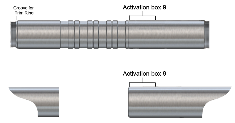
Another option re: the 2" DF is to lose it and the DM adapter and have Tim customize a 9" DF extension with the appropriate groove pattern and hole locations. As a plus, you'd only have one body part to deal with and might be cheaper. You'd lose 1/4" in length though. Negatively, if a chassis design depended on those intermediate lock point locations you'd have to redesign it or find another way to anchor it. Or do what I did on my first saber - use so much wire because you were terrified of messing up and subsequently filled the guts of the thing and the board couldn't move. Not really what cram-fu means though.
Oh - don't forget to recalculate the resistors for BOTH the rebel AND the led in the switch. And remember to install them... or joint this noob in the deep fat fried switch club.
-
9" main body is a great idea! I think the only issue that I'd have would be the trim ring that sat between the M2M and the main body which was meant to but maybe I can think of something else. ElbE121's Meraxes Saber design gave me a great idea to smooth out the sleeve material so where it stops on the handle it can kind of slope down the main body and give it a very seemless look. The other thought I had, now that I know Tim does a lot of custom work, is for the end of the 9" body where the pommel fits on, maybe have him lathe a slot after the threading for the trim ring to go? This would alleviate the problem of the speaker in the pommel.
I know where to calculate resistors, the issue is that I don't know exactly how much juice it's going to have. Reference image below.
http://i416.photobucket.com/albums/p...01-10-2011.png
Based on this, I need a transistor which I can't seem to find in the store. tbh, I have no idea where a transistor would go inside the saber or even what it does, lol. Does it change the voltage at all? It does look pretty important, though... I've tried looking it up but it seems like it's one of those things that isn't talked about a lot because it's probably basic knowledge to a lot of people but I'm at a lost when it comes to this.
Anyways, thanks again amwolf!
-
Jedi Initiate

-
That makes sense, I just have to think of a way to fit it in there. Can I just shrink wrap it and just shove it in there once I it's all wired up?
Okay, now I'm having a huge problem with trying to figure out the resistors I need. I know I'll need 2, one for each LED, but I can't find a calculator that actually works (or I'm just inputting the information wrong). The Rebel Star reads "Green 166lm @ 700mA 3.4v" and the switch reads as "The LED has a forward voltage of 3.3V and runs at 20mA". Does these mean a 3.7v Li-ion isn't enough power or that I need a resistor? I don't know if I'm supposed to add the voltage of both LED's and try to get it to match the voltage of the batteries, using a resistor if there's extra voltage, or if the voltage of each runs independently meaning I need a resistor for each to balance the 3.7v battery down to 3.3v and 3.4v respectively. I'm a complete noob when it comes to electronics.
-
If you are getting an illuminated switch you will also need a resistor for it as well as a separate resistor for the main LED. The 1ohm 5w resistor in your list is ok for the Rebel star with a 3.7v battery pack. The green illuminated switch needs its own resistor, its forward voltage is 3.3v and runs at 20mA. So you need a 22ohm 1/8w (or higher watt) resistor so you dont fry the led in the switch.
You may also be interested in in getting a Buck Puck instead of the resistor for your main LED. Its more expensive, but it will give you a more constant brightness as the batteries die. With only a resistor the brightness will dim as the batteries die.
Good luck 
EDIT: Here is the resistor calculator i use: http://led.linear1.org/1led.wiz
Last edited by crobemeister; 07-30-2011 at 11:06 AM.
-
Jedi Initiate
Your question is a valid one for someone with little to no electronics experience, but it's also relatively easy to answer.
There are two different ways to wire multiple components to a power source; series (serial), and parallel.
In series (each component is linked together + - + - + -)the voltage behaves additively/subtractively, with the total voltage being divided by the total components.
In parallel (components tied side-by-side instead of back to back ++ -- ++ --) the voltage is the same to each component, and more current (mA) is drawn from the batteries.
You'll be wiring your led's in parallel, in order to maximize your voltage constraint. That means you're going to need resistors to drop the parallel power levels down to what each component needs.
While it isn't completely necessary for a successful build, it would also be worth your time to study Ohms law, to learn how voltage (V, v+, v-) and current (I, mA, A) relate to each other in batteries, and work loads.


 Give a man a fish and he eats for a day. Teach a man how to build a lightsaber and he will forever feast on tauntaun carcasses and aqualish arms. TimeRender
Jesus pogostick what kind of Rodian clusterbomb is this? DD
TCSS: It's all my favorite people I've never met, all in one place
Give a man a fish and he eats for a day. Teach a man how to build a lightsaber and he will forever feast on tauntaun carcasses and aqualish arms. TimeRender
Jesus pogostick what kind of Rodian clusterbomb is this? DD
TCSS: It's all my favorite people I've never met, all in one place
-
Thank you Kuro and Crobe for the advice, I'll be adding the switch capacitor to my list. As for the Buck Puck, it says it has a minimum input of 5v so only having a 3.7v battery wouldn't work, right? I could easily upgrade to two 3.7v batteries if that buck puck takes all the confusion out of getting a capacitor. What confuses me about the buck puck is that it has 4-6 wires and I can only think of a use for 2, maybe 4 if the other two are used for a separate LED. If all I need is a 4-wire buck puck for my two LED's, I'd much rather go that route than mess around with capacitors which means two batteries (longer time without having to charge =D).
The more I try to figure this stuff out, the more I realize it will most likely be one of those things that I'll understand after I do it the first time.
Edit: Made updates to the dimensions so people have a better idea of what I'm doing with the overall design of the hilt. Thanks to amwolf for the recommendation on the 9" body.
Last edited by whenbearsreign; 07-30-2011 at 10:02 PM.
Tags for this Thread
 Posting Permissions
- You may not post new threads
- You may not post replies
- You may not post attachments
- You may not edit your posts
-
Forum Rules


 Reply With Quote
Bookmarks