Page 1 of 3 1 2 3 LastLast
Results 1 to 10 of 23

Thread: reed relays

  1. #1
    Force Aware
    Force Aware
    JudgeKane's Avatar
    Join Date
    Jun 2008
    Location
    Thirsk, North Yorkshire, UK
    Posts
    123

    Question reed relays

    Ok, found some 5v reed relays in the UK (for the board/LED - keeping it bright), now I have the option of "Reed Relay 5V SPST" or "Reed Relay 5V DPST"...

    Which should i be buying, and if you can put it in layman's terms, whats the difference?

    I know it's to do with the switching, one just "pings a signal" and the other stays on...maybe lol i'm not sure
    Judge them from the Darkness...

  2. #2

    Default

    You appear to have asked a question in a vacuum, so to speak. We're going to need a good bit more information before answering.

    http://en.wikipedia.org/wiki/Relay and http://en.wikipedia.org/wiki/File:Relay_symbols.svg can help with understanding the difference between SPST and DPST.

    What exactly are you wanting to do? Most uses of relays in the lightsaber hobby have been changed to use transistors for the sake of durability.
    We all have to start somewhere. The journey is all the more impressive by our humble beginnings.

    http://led.linear1.org/1led.wiz for the lazy man's resistor calculator!
    http://forums.thecustomsabershop.com...e-to-Ohm-s-Law for getting resistor values the right way!

  3. #3
    Force Aware
    Force Aware
    JudgeKane's Avatar
    Join Date
    Jun 2008
    Location
    Thirsk, North Yorkshire, UK
    Posts
    123

    Default

    Basically I've just put a economy sound board into my 1st saber (2nd get's one soon) and just been reading through the sound forums about sound boards and getting the LED to run brighter, and the relay idea seemed like a good idea, I shall have a look into transistors and have a re-think lol
    just found this http://forums.thecustomsabershop.com...highlight=2010

    What sort of transistor am i looking for? searched on a UK supplier and they have 18 different types lol

    Low-Power, Low-Frequency PNP Transistors; BC558C, BC327, 2N5401
    Standard Bipolar PNP Power Transistors; BD442, TIP2955, BD912 there's billions!!!!!! lol
    Last edited by JudgeKane; 07-19-2011 at 11:42 AM.
    Judge them from the Darkness...

  4. #4

    Default

    Look at the data sheet it will show the difference. Ether should work. and make sure you get one that can handle more current than you need.

  5. #5
    Force Aware
    Force Aware
    JudgeKane's Avatar
    Join Date
    Jun 2008
    Location
    Thirsk, North Yorkshire, UK
    Posts
    123

    Default

    I'm lost with these transistors they say weird things like -100mA...eh? lol

    Think I might try the relay method, I understand how that works lol and they don't get flung about too much so should be durable enough...
    Judge them from the Darkness...

  6. #6

    Default

    For future reference, anything in electronics that says SPST, SPDT, DPDT, SPTT, DPTT... etc; is referring to Single Pull Single Throw, Single Pull Double Throw, Double Pull Double Throw, Single Pull Triple Throw, and so on.
    The "pull" refers to the physical component of the switch, be that a button, toggle, signal (as in solenoids and relays), magnet (as in reed switches), or any other input device or sensor.
    The "throw" is the circuit connection, which you're completing or breaking.
    SPST means there's one button for one circuit, while SPDT is referring to a single switch that simultaneously toggles two different circuits.
    On a non illuminated switch, SPST means only two pins, while SPDT means four (unless it's bi-directional, then it's six).
    There will always be at least two pins for every throw, three if it's bi-directional.
    In the case of a relay, solenoid, or illuminated switch, there will be two extra pins for the signal coil or LED power.


    Give a man a fish and he eats for a day. Teach a man how to build a lightsaber and he will forever feast on tauntaun carcasses and aqualish arms. TimeRender
    Jesus pogostick what kind of Rodian clusterbomb is this? DD
    TCSS: It's all my favorite people I've never met, all in one place

  7. #7

    Default

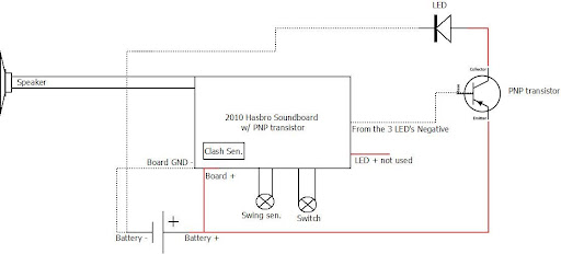
    If you look in the forums in tutorials you can find a couple of diagrams showing transistors instead of reed relays. Trust me the transistors work the best. Most of the time you can find them at RS. Its called a TIP42. Good luck.

  8. #8
    Force Aware
    Force Aware
    JudgeKane's Avatar
    Join Date
    Jun 2008
    Location
    Thirsk, North Yorkshire, UK
    Posts
    123

    Default

    Thanks KuroChou, that was great, and i think it's actually sinking in

    and thanks Noyl Wendor, I shall have a look over the next couple of days and give the transistor a bash then, looking at the diagrams;

    The battery poss goes to the transistor then onto the LED, would this setup not need a buckpuck after the transistor or a resistor at least? (I don't wanna pop anything, i haven't sourced the LED's in the UK yet
    Judge them from the Darkness...

  9. #9

    Default

    You definitely need to add at least a resistor between the LED and the transistor.

    The choice of the resistor depends on the LED type and color and the battery solution you are planning to use.

    For reference you can check the LED resistor chart in the shop.

  10. #10
    Force Aware
    Force Aware
    JudgeKane's Avatar
    Join Date
    Jun 2008
    Location
    Thirsk, North Yorkshire, UK
    Posts
    123

    Default

    I think i'll try running a 1000mA buckpuck and see what happens...i'll get some pics/vids up when i've had a go
    Judge them from the Darkness...

Bookmarks

Posting Permissions

  • You may not post new threads
  • You may not post replies
  • You may not post attachments
  • You may not edit your posts
  •