I'd love to, but I can't find a photo online...Originally Posted by Azmaria Dei


.exe's Avatar")


I'd love to, but I can't find a photo online...
When your lightsabers gutter and die in your hands,
your blaster packs run dry of charge,
your words of power dry up in your throat and I am still standing,
what will you do then?
Technically I'm doubleposting, but since this is a big update, I hope you all can forgive me.
Behold! Megami Internals v1.0!
Once everything is put together, the saber would be assembled as follows:
1. Pommel w/ Insert + Trim Ring screwed to Fluted Section, creating Lower Hilt
2. Emitter screwed to Ribbed section w/ LED+Heatsink combo and all switches/ports already installed, creating Upper Hilt. Labeled quick connect leads extend from ribbed section
3. Electronics sled consisting of Accent LED array, battery pack+PCB, PC-L and speaker+mount are slid into Lower Hilt. Labeled quick connect leads extend from between speaker and mount.
4. Quick connects are attached to each other and twisted in opposite direction of threading, mid trim ring is slid over Upper Hilt threading.
5. Upper and Lower Hilts are screwed together, saber assembly is complete.
NOTES/QUESTIONS:
1. Will the v3 Speaker Mount work for my reverse sound setup in that configuration? (Transparent orange near middle of hilt)
1a. Yes, I plan on drilling through the back of the v3 mount, pushing the threaded rods for the electronics sled through, then bolting them together with the 4-40 nuts. If someone has a better idea, please share
2. The shim ring is something I'll create out of scrap metal/plastic, to ensure the electronics sled remains in place.
3. I plan to wire up all the switches, ports and main LED with quick connects, so that I can disassemble the saber by unscrewing the middle, d/cing the quick connects, then pulling out the electronics sled in the aft portion of the hilt.
4. Resonance chamber holes in the top of the ribbed section will be covered by the shroud over that area.
Sleepytime now, see you all tomorrow!
When your lightsabers gutter and die in your hands,
your blaster packs run dry of charge,
your words of power dry up in your throat and I am still standing,
what will you do then?

Nice render - looking forward to seeing this one done!
-C
LOCKHEED
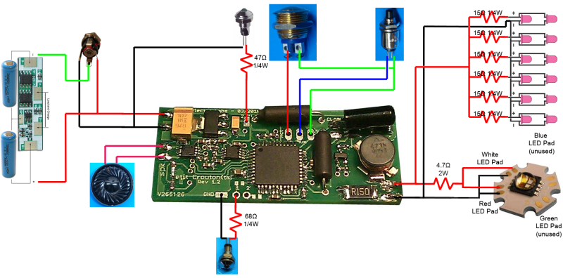
Wiring Diagram!
Someone who actually knows what they are doing please doublecheck my work.
Main LED is CREE RGBW with the following stats:
Red Pad: 2.3Vf @ 700mA
White Pad: 3.5Vf @ 700mA
Blue Pad: 3.5Vf @ 700mA
Green Pad:3.7Vf @ 700mA
Main LED is currently resistored using the numbers for the Red pad at max output, which means it's underdriving the White pad. I'm hoping the max output red + mid output white will combine favorably to get a pink. I'm not adverse to wiring and resistoring each pad separately, I just need to figure out the individual resistors to do so.
I'm trying to get a pink to match the accent LEDs (440nm) so if anyone has any suggestions on how to resistor the pads to get that or close, I'd be greatly appreciative. I'd love to build some kind of box with 4 pots on it to twiddle around with color tuning and figure out the resistance required, but that's too much for the time I have for this build.
Pink Accent LEDs for the Pommel Array are: 440nm Wavelength 4.0Vf @ 20mA
Battery Pack is a pair of Tenergy 14500s wired for 7.4V
Last edited by (null).exe; 06-09-2011 at 11:03 PM.
When your lightsabers gutter and die in your hands,
your blaster packs run dry of charge,
your words of power dry up in your throat and I am still standing,
what will you do then?

Gorgeous feminine design. I see a little Ahsoka Tanno influence there.
"So he drove out the man; and he placed at the east of the garden of Eden Cherubims, and a flaming sword which turned every way, to keep the way of the tree of life." -- Genesis 3:24 Lightsabers are real.

first off, lose the resistor on the main LED. the PC has a fully capable LED driver. second off, i HIGHLY recommend you run the blue and white in series. AKA run the positive end of the white to the negative end of the red, the neg on the white to the neg LED out, and the pos on the white to the pos LED out. then set your LED current output to 1100mA if it's an RGBW CREE - you won't be disappointed. ^_~
as for your accent LED resistors, i think you need to recalculate them based on the combined fV of the R and W dies (5.8V) for the array, and based on the 3.3V 18mA max output on the accent pads.
also, the pads on the CREE LEDS are all pos one side, and all neg on the other. looking at the pos end closest to you, the order is literally R G B W. ^_~
looks good other than that though.
CLICK HERE FOR ALL YOUR ECONO SOUND BOARD WIRING DIAGRAM NEEDS!
Duel - to fight someone 1 on 1. Dual - 2 of something in line with each other.
Wasn't there a post somewhere on the forum where it was recommended to run some form of resistance between board and LED to prevent heat buildup in the board itself? Or am I just making things up?
So run 3 of the 4 pads together? You think that'll get a better pink color than just RW on their own?second off, i HIGHLY recommend you run the blue and white in series. AKA run the positive end of the white to the negative end of the red, the neg on the white to the neg LED out, and the pos on the white to the pos LED out. then set your LED current output to 1100mA if it's an RGBW CREE - you won't be disappointed. ^_~
That's what I was feeling uneasy about, I calculated the Pink array resistance based on the 7.4v from the battery, not the Vf of the dies.as for your accent LED resistors, i think you need to recalculate them based on the combined fV of the R and W dies (5.8V) for the array, and based on the 3.3V 18mA max output on the accent pads.
And for the accent LED indicators, I think I did do it correctly: Green LED is 2.2v@25mA, Red is 2.0v@20mA. Pad provides 3.3v, which when I run that through the LED calc, returns 47Ω@1/4W for Green and 68Ω@1/4W for Red. What am I missing/doing wrong?
Well, serves me right for not researching the LED pad setup enoughalso, the pads on the CREE LEDS are all pos one side, and all neg on the other. looking at the pos end closest to you, the order is literally R G B W. ^_~
Thanks for all your help!
When your lightsabers gutter and die in your hands,
your blaster packs run dry of charge,
your words of power dry up in your throat and I am still standing,
what will you do then?
that was for ACCENT LEDs. the main LED is driven by a REAL LED driver.
no, i mean instead of running the 2 pads in parallel, run them in series. it'll be brighter and more efficient with a 7.4V battery pack.
you're running the pink LED array off of the main LED driver - use the formula in the manual to calculate the resistors needed, OR calculate the fV draw that the main LED demands the LED driver put out.
$Deity, you're lucky i'm here... T_T
CLICK HERE FOR ALL YOUR ECONO SOUND BOARD WIRING DIAGRAM NEEDS!
Duel - to fight someone 1 on 1. Dual - 2 of something in line with each other.
Oh, okay. Getting rid of the main LED resistor.
Done and done!
R = (Vsupply Vled) / LedCurrent -> R = (5.8v(combined RGBW draw) - 4.0v(pink LED draw)) / 40mA (Pink LEDs in parallel) -> R = 45Ω
Yes, yes I am
When your lightsabers gutter and die in your hands,
your blaster packs run dry of charge,
your words of power dry up in your throat and I am still standing,
what will you do then?
MUCH better. good job, you're learning. ^_^
CLICK HERE FOR ALL YOUR ECONO SOUND BOARD WIRING DIAGRAM NEEDS!
Duel - to fight someone 1 on 1. Dual - 2 of something in line with each other.


 Reply With Quote
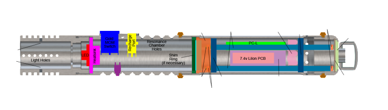


Bookmarks