Results 1 to 10 of 10

Thread: TCCS Accent LEDs and the Petit Crouton

  1. #1

    Question TCCS Accent LEDs and the Petit Crouton

    Hi Everyone,
    I'm at the end stage of my niftyneato sith saber build, and have encountered a problem and want to mine the collective wisdom.

    Do the small red, yellow, and green accent LEDs the store sells work with the Petit Crouton? I have the darkmeat flavor board, and have a red and yellow LED from the store wired up,
    and although all other functions of the PC operate, neither of them work, either with the correct resistors, or without.
    All of them call for >20ma,
    but the board puts out just 18ma.
    Are you all running these?
    if not, then what are you using with the PC-L?

    Thanks,
    ~Alison
    DS

  2. #2

    Default

    the LED's in the store will all work with the PC-L. If I remember correctly (consult your manual) you don't need resistors on the accent LED's...but double check first, I might be wrong.
    Yub Yub Commander.

  3. #3
    Jedi Knight cannibal869's Avatar
    Join Date
    Sep 2008
    Location
    Home of NUCLEAR JEDI SABERS
    Posts
    1,027

    Default

    the "problem" is actually usually more with regards to the driving voltage, not the current. The difference between 18 and 20 mA is pretty miniscule. Most of the 3mm and 5mm LEDs I've seen list the current as 20mA. Ideally your "best" LEDs for the PC-L, PC-U, and CF will have a driving voltage of 3.3V and current of 20mA (therefore won't need resistors )
    LOCKHEED

  4. #4
    Jedi Knight
    Jedi Knight
    Azmaria Dei's Avatar
    Join Date
    Dec 2010
    Location
    Zama City, Japan, Sol 3, Gould Belt, Milky Way Galaxy, Virgo Supercluster
    Posts
    1,022

    Default

    ok now... i've wired up 6 PC-Ls now and when i wire up ANY accent LED without at least a 15 ohm resistor the PC gets hot quick because of the LED trying to draw too much current.

    hence my standing advice of ALWAYS using a resistor to prevent potential heat damage from trying to pull more than 18mA through the main chip.
    CLICK HERE FOR ALL YOUR ECONO SOUND BOARD WIRING DIAGRAM NEEDS!

    Duel - to fight someone 1 on 1. Dual - 2 of something in line with each other.
    Quote Originally Posted by Multiple People
    To Azmaria listen you should...

  5. #5

    Default

    My only guess is the LED isn't wired properly. Make sure your positives and negatives are wired properly...that should be common sense but if it's not that I'm guessing the LED is being fried instantly but you'd see a flash and fade of the LED....maybe the bridge on the SMD resistor pads. Strange. I used no resistor and no problems at all. I'm curious to hear some more about this myself since I've only used the accent LED pads once so far.

  6. #6

    Default

    thanks for the replies everyone, I 'ppreciate the help.

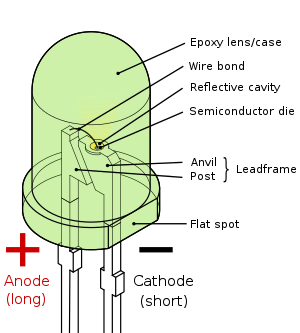
    I am pretty sure they're wired properly, but that's open to correction. do the small LEDs have a + and -? how can you tell which is which? if you only currently (ha!) have an analog multimeter?

    for those who have used the accent pads, did you use the store's LEDs? We tried a green one too - the old "known good" swap, and it didn't work either. I fear we damaged the board, which would make me a very sad panda indeed.

  7. #7

    Default

    The longer of the two is the positive...if you cut them short or wired them to leads and can't tell, then the negative is usually the larger piece inside the plastic. The little square patch of solder next to LED2's positive pad is bridged to bypass what was made to be a SMD resistor. I can't imagine bridging your lead to it would do any harm but breaking that bridge (there' two micro pads under it) breaks the circuit....if you're really stuck a picture can save us all a thousand words.
    Last edited by Crystal Chambers; 05-27-2011 at 05:21 AM.

  8. #8
    Council Member
    Jedi Council Member
    Jedi-Loreen's Avatar
    Join Date
    Dec 2005
    Location
    Not of this Earth
    Posts
    6,077

    Default

    There's another way to tell which lead is which on an LED after you've cut them short:


    Look for the flat spot, that's the negative side.
    In order to see the Light,
    you must sometimes risk the Dark.
    TCSS MODERATOR


    BLUE 8 Ready to ROCK and ROLL!

  9. #9

    Default

    Quote Originally Posted by Crystal Chambers View Post
    .... the negative is usually the larger piece inside the plastic. ....if you're really stuck a picture can save us all a thousand words.
    Exactly J-lo....awesome diagram! I only knew names for the anode and cathodes. I hadn't thought of the flat side as being an indication of that. I'm guessing that's a good sign when the post and anvil appear the same like in blinky LEDS for instance.

  10. #10

    Default

    yes, thanks for the diagram, that's good to know,
    and it turned out that my gf reversed the leads. she resoldered them and voila'!
    electrical problem rectified (ha!) and the saber is together and functioning wonderfully! i am making 3 emitter claws for it, and need to get to the hobby shop tomorrow for some cap head screws, but once it's done i'll post pics and video for your amusement/ridicule. ^_^
    thanks for the help,
    ~DS

Bookmarks

Posting Permissions

  • You may not post new threads
  • You may not post replies
  • You may not post attachments
  • You may not edit your posts
  •