


Lithium Ion Battery Packs
How to make them and use them safely
For basic soldering to batteries, please see this thread. The same principals for soldering NiMH cells applies to Li-Ion cells, it's just a little more violent when you mess them up bad as Lithium is combustible with air and water. Fortunately, cells these days are made with a tough casing that takes a lot to puncture, as well as being vented on the positive end so that the lithium has a little room to expand. If, however, you somehow make the vented cells squirt out some of the dielectric inside, wrap it up, seal it, wash your hands and scour any surfaces thoroughly, and take the cell to a disposal facility ASAP. That stuff burns and will eat through a lot of things - i've seen it melt the PVC heat shrink on a cell before so it's nothing to play with. If you ever wondered why you can't send cells through airmail normally, this is why - the air pressure drops in a cargo jet and pulls the gel out, potentially letting the lithium come into contact with air that gets sucked back in when the jet lands.
Now that you're sufficiently scared of what can happen if you mess up badly, here's why you want to use Li-Ions. They output 3x as much voltage as most other cells on the market right now while having slightly lower capacities. Their outputs are also rather high due to the really low internal resistance. What does this all mean? That a single AA sized cell will put out a nominal voltage of 3.7V. This is only the common voltage of them though. an actual Li-Ion will vary the voltage from 4.2V at full charge to 2.7V for a completely dead cell. The voltage CAN drop lower, but the risk of damaging the internal materials of the cells rises dramatically. On that note, I've revived and reused Laptop cells that had dropped to .8V and I use them in several sabers now.
Unlike other cells, Li-Ion cells need a PCB (normally this stands for Printed Circuit Board, but in the battery communities it's normally Protection Circuit Board) to prevent it from do ing several things that can either damage the cells, the items powered by them, or potentially the user/operator. This is like a life preserver for the cell. A smart charger has similar circuitry built into them so you can charge unprotected cells with them before you make a pack yourself. There are several standard markings on Li-Ion PCBs and they are thus. B+/B- - these are the terminals you solder the positive and negative battery terminals to. P+/P- - these are the leads for the pack as a whole and go to your device/electronics being powered. BM/B1/B2/etc... - these are the Battery Middle pads where you hook the interconnecting joints between the cells in a multi-cell pack that goes over 3.7V - I'll talk more on these later, but these are basically so that the PCB can power balance the cells (minor adjustments only) and keep them at the same charge level/capacity.
Li-Ion cell sizes are labeled a little differently from other cells as well - normally in a 5 digit code. The first pair of digits are the diameter, the second pair are the length, and the last position is cell type - 0 meaning round. Some standard sizes are 18650 (18mm diameter, 65mm long, and cylindrical cell), 18500, 14500, and 18350.
If you see a Li-Ion cell that says 3.6V instead of 3.7, then that's likely a camera battery and not worth your time. The PCBs in those NORMALLY limit the cell to something like 600-800mA outputs and clip the output voltage at 3.6V so you can't get the full potential out of them. Regular lithium batteries are Li-MnO2 (heat treated Lithium Manganese Dioxide) and these are NOT rechargeable, though they are 80% of the Lithium market. These are normally 3V button cells. Energizer lithium batteries are Li-FeS2 - Lithium Iron Disulfide, and are 1.5V AA or AAA batteries - these are normally not rechargable, but if it's marked as Li/Fe, that's actually lithium iron sulfide. Lithium Polymer batteries are reportedly still too unstable and prone to destroying themselves or other things, so stay away from them as well.
And now we'll look at how to make a battery pack. We're going to do a 7.4V pack, since that's one of the two most common setups in sabers as well as the more complex of the two.
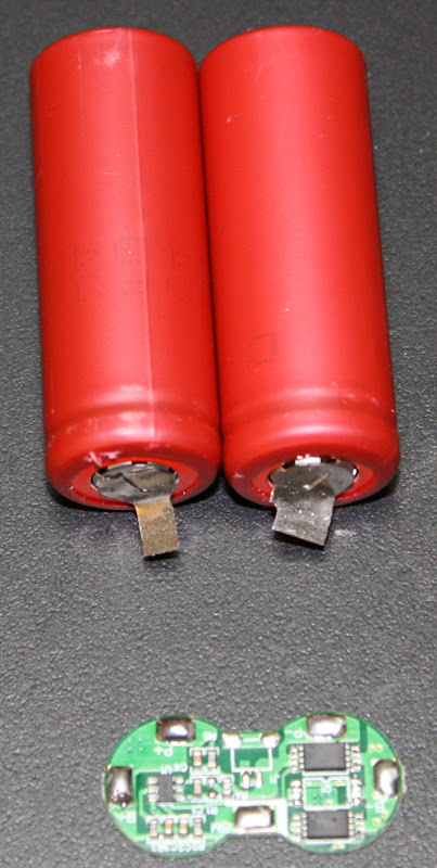
Here we have 2 18500 cells and a 7.4V figure-8 PCB normally made for the end of battery packs. Since I’m making a stick pack, but prefer these PCBs because of the 13A output cutoff, I won't be doing that. Instead I'll be wiring it a little separate from the cells and adding it into the chassis that this pack is intended for. You'll notice that these cells have tabs on them. I like the tabs as it's a little easier to solder to the tabs at times. These are also all recycled tabs from defunct devices like camcorders and laptops.
Like in the other tutorial, file the ends of the cells (or the tabs) so the solder has something to stick to, and tin them as you would any other connection. Once you do that, you can solder the wires all together the first battery (left in the picture) goes from the positive (indicated by the ring in the casing) to the B+ terminal on the PCB. The negative end of battery 1 gets wired to 2 places - the BM pad on the PCB and the positive end on battery 2. This is the control and multi-cell monitoring lead that I mentioned earlier. Then wire the negative side of battery 2 to the B- pad on the PCB.
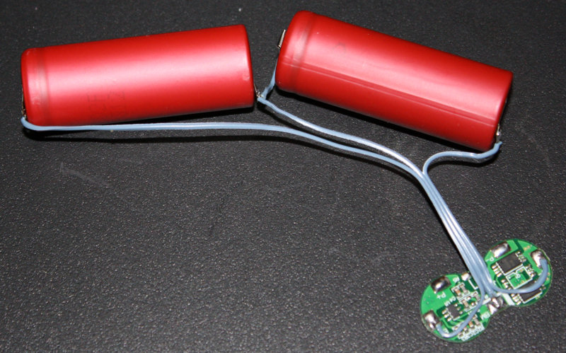
That's it for the battery side of the cells. You can now heat shrink them with your favorite PVC battery heat shrink. For most packs I use 37-42mm heat shrink.
And here's the final setup for this battery pack. It will eventualy be secured to the chassis and the power leads for the recharge/kill port soldered to the P+ and P- pads on the PCB.
Here's a look at a 2 cell 3.7V Li-Ion pack. both cells are wired in parallel for twice the capacity, but base voltage. This one is using a small rectangular 3.7V PCB good for packs like this.
Notice how each end has the same polarities soldered to each other.
Here's the same PCB on a single cell setup. notice that the same pad is used for B+ and P+.
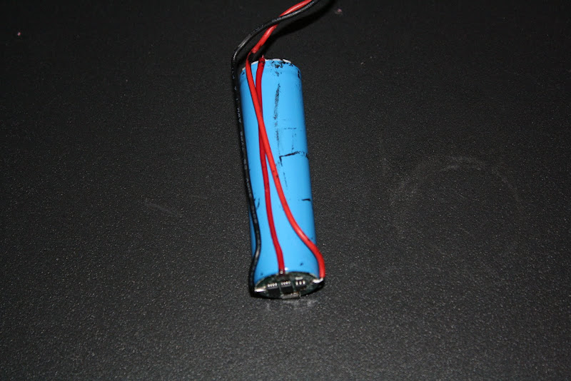
This is a single cell pack made with an old 18650 cell and a small round PCB.
It's an older pack, and the wiring sucks because my iron tip was dying, but the principal is the same. It goes on the negative end and I've folded the negative tab over and soldered it in place to the B- pad. The B+ pad is wired to the positive end. Finally, the P+ and P- pads are wired to a JST connector.
And here's that same laptop cell rebuilt and ready for use in a saber.
Upcoming FAQ will have more info.
Az


 Reply With Quote
Bookmarks