Page 1 of 3 1 2 3 LastLast
Results 1 to 10 of 28

Thread: Hasbro Economy Board; "Rewire Tutorial"

  1. #1
    Jedi Council Member cardcollector's Avatar
    Join Date
    Jan 2009
    Location
    I am A proud American.
    Posts
    2,567
    Blog Entries
    3

    Default Hasbro Economy Board; "Rewire Tutorial"

    Hey all,

    Just the other day I was rewiring a economy board for a customer, and decided to take a few pics on how I did it.

    Rewiring a board basically means in this case removing all components of a board and replacing them with better components and wires that won't break as easily. I do this with all my sound installs. It usually takes me 20-30 minutes. I use 26 gauge wire, like the stuff sold in the TCSS store.

    So, let's begin.
    The first thing to do it to get a board. I will be using the 2010 Obiwan board with DVD. Other boards can be treated similarly though.


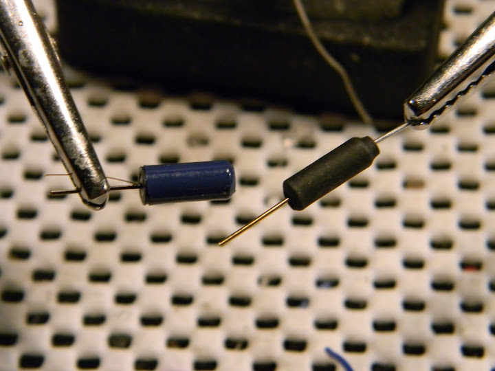
    After the board is removed from the hilt, I like to start with the clash sensor. The Hasbro clash sensor isn't as good as the TCSS sensor, nor the hasbro swing sensor as good as the TCSS swing sensor... So get two of each. (in case one is broken in the process of installing it.)


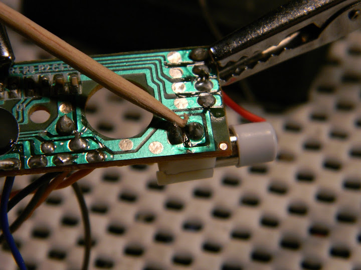
    Now, if the board is flipped over, we can see two traces that hold the clash sensor. We will want to remove all the old solder so the old clash sensor falls out.


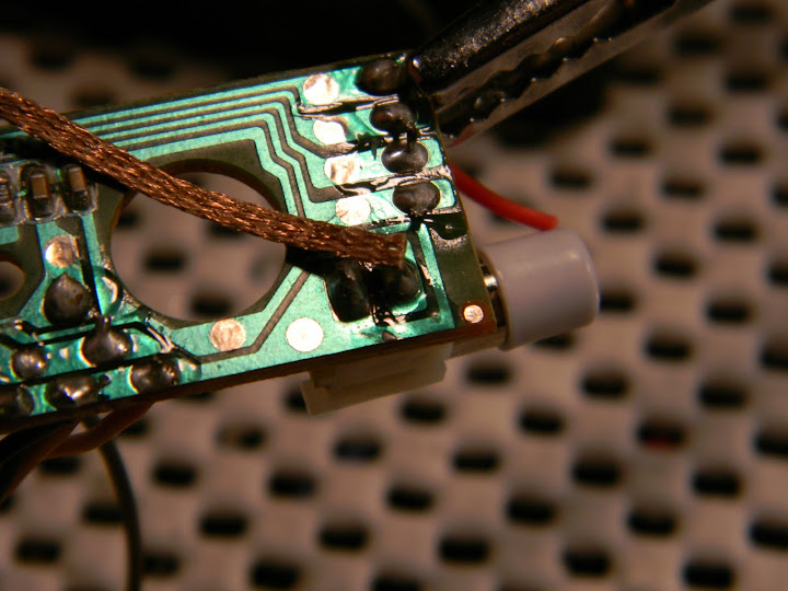
    Grab your solder iron, and some solder braid (great stuff!) and suck up all the old solder...


    If your iron is the right temperature, the solder should be absorbed right into the braid. Leaving you two empty traces.


    Now, just slip the new clash sensor into the holes and viola, much better clash sensitivity!


    Next we will go the the PNP transistor setup. I like to mount it on the board because There is less chance of it becoming damaged...
    SO, first, remove all the LED wires with the solder braid.


    Now take some needlenose pliers and the transistor and bend the leg and insert the leg into the LED - as shown...


    Flip the board over, and solder all the LED negative traces together. This step isn't necessary, but I like to do it just for good measure.

    and solder the traces together.

    Now, take the other leg, and bend it the direction of the Batt +. Add a wire like so;

    Don't forget to add heatshrink! You will also want to insualt the metal heatskink tab on the PNP transistor. You can do this with hot glue.


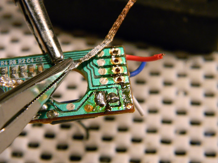
    The next part is my favorite. Proceed to remove ALL wires on the board, it will wind up looking like this.

    It is easy to see where everythin goes back in place now. So, it is a simple matter of replacing the wires with the colors of your choice.

    This is what the swing sensor looks like when added to the board.

    Here is a great suggestion from Cannibal
    "A suggestion - use 2 swing sensors - mount them perpendicular to each other so that they form sort of an "L" or "V" shape. Now bend the leads together so that you have one set of leads near the 90 degree angle where the two sensors meet and the other set sort of meeting in the middle. Solder into the board in the appropriate locations."


    That's it guys, hope you found this little tutorial useful!
    Last edited by cardcollector; 04-24-2011 at 12:00 PM.
    Got a Question? There's a thread for that...
    ~Do what you can, with what you have, where you are.~Teddy Roosevelt

    SollusVir everywhere else... FXsabers, Youtube, etc...

  2. #2

    Default

    very nice tutorial CC

    I usually replace the wires but never thought of using the Tip42 that way very ingenious
    I will have to try it next econo setup i use
    nice point of replacing the sensors

  3. #3
    Jedi Knight
    Jedi Knight
    Azmaria Dei's Avatar
    Join Date
    Dec 2010
    Location
    Zama City, Japan, Sol 3, Gould Belt, Milky Way Galaxy, Virgo Supercluster
    Posts
    1,022

    Default

    excellent tutorial! i do have a comment though, if i may. i've run into a few transistors/MOSFETS that the back plate/metal tab is another contact so i would suggest isolating them in some way if you get continuity between that tab and any lead.
    CLICK HERE FOR ALL YOUR ECONO SOUND BOARD WIRING DIAGRAM NEEDS!

    Duel - to fight someone 1 on 1. Dual - 2 of something in line with each other.
    Quote Originally Posted by Multiple People
    To Azmaria listen you should...

  4. #4
    Jedi Knight cannibal869's Avatar
    Join Date
    Sep 2008
    Location
    Home of NUCLEAR JEDI SABERS
    Posts
    1,027

    Default

    I would also add the following suggestion - use 2 swing sensors - mount them perpendicular to each other so that they form sort of an "L" or "V" shape. Now bend the leads together so that you have one set of leads near the 90 degree angle where the two sensors meet and the other set sort of meeting in the middle. Solder into the board in the appropriate locations.

    what I'm trying to do with this is give you a bit better response as far as motion and swing sensitivity - this also replicates the orientation of the swing sensors in the MR and PC boards.

    This way you get more accurate swing - the hard part is just bending the wires to fit into the board.
    LOCKHEED

  5. #5

  6. #6

    Default

    Dear Cardcollector,

    Thanks for your tutorial! i wish I had seen this before I started my build this weekend...

    I have a few questions for you:

    Can you purchase the solder braid at local stores? Where did you get yours? ( I see Tim doesn't sell it in his store so I hope I'm ok asking...)
    There looks like some kind of liquid something on your board after you've removed the old solder. Is that like a superglue to help hold things in place?

    Thanks!
    CM


    Remember, your LED will ALWAYS look brighter in pics and vids... If you're not playing with it at night, it's not gonna impress you...

  7. #7
    Jedi Council Member cardcollector's Avatar
    Join Date
    Jan 2009
    Location
    I am A proud American.
    Posts
    2,567
    Blog Entries
    3

    Default

    Hey, you are more than welcome.

    I bought my solderbraid at mpja.com. It is readily available at other website though, just do some looking around and get the size and kind you like best.

    The liquid looking stuff is the clear insulation that was melted when I was removing the solder. Nothing major, it'll just happen.

    Oh AZ and cannibal, those are great ideas. I will add them as soon as I get on a computer.
    Got a Question? There's a thread for that...
    ~Do what you can, with what you have, where you are.~Teddy Roosevelt

    SollusVir everywhere else... FXsabers, Youtube, etc...

  8. #8
    Jedi Padawan
    Jedi Padawan
    Boj-Vaati Mau's Avatar
    Join Date
    Oct 2010
    Location
    United States
    Posts
    608

    Default

    Excellent ideas folks! I love the placement of the TIP, cuts down a bit of extra wire. I'll incorporate these into the mods for my BYTB saber I plan on upgrading for my wife.

    Knowledge must be balanced by Practice.
    Practice must be balanced by Experience.
    Through Knowledge, Practice, and Experience
    we gain Wisdom.

    -Boj-Vaati Mau
    Jedi Sentinel, Jar'Kai practitioner,
    and Instctor at Strafe Plains Temple


    Saber Guild: Strafe Plains Temple
    The Rebel Legion

  9. #9

    Default

    Quote Originally Posted by Azmaria Dei View Post
    excellent tutorial! i do have a comment though, if i may. i've run into a few transistors/MOSFETS that the back plate/metal tab is another contact so i would suggest isolating them in some way if you get continuity between that tab and any lead.
    IIRC that is a convention. The back plate is connected to the collector (or FET equivalent) so they can all be safely mounted to metal heatinks without shorting.

    Click here to learn all about me!
    The Shoutbox: The only place you can double post!
    Anybody who spells it Lightsabre is dyslexic
    "Yeah, if I had Skotts face I'd hit it too" ~ Fenderbender
    "You didn't buy a toy saber just to break it. You bought an economy sound card with a really complicated wrapping scheme." ~ Silver Serpent

  10. #10
    Jedi Knight
    Jedi Knight
    Azmaria Dei's Avatar
    Join Date
    Dec 2010
    Location
    Zama City, Japan, Sol 3, Gould Belt, Milky Way Galaxy, Virgo Supercluster
    Posts
    1,022

    Default

    Quote Originally Posted by Skottsaber View Post
    IIRC that is a convention. The back plate is connected to the collector (or FET equivalent) so they can all be safely mounted to metal heatinks without shorting.
    heatsinks yes, but feeds from other points on the board would be bad.
    CLICK HERE FOR ALL YOUR ECONO SOUND BOARD WIRING DIAGRAM NEEDS!

    Duel - to fight someone 1 on 1. Dual - 2 of something in line with each other.
    Quote Originally Posted by Multiple People
    To Azmaria listen you should...

Bookmarks

Posting Permissions

  • You may not post new threads
  • You may not post replies
  • You may not post attachments
  • You may not edit your posts
  •