Page 1 of 4 1 2 3 ... LastLast
Results 1 to 10 of 34

Thread: German Padawani needs some Advice :)

  1. #1

    Default German Padawani needs some Advice :)

    Hey guys and gals!

    Firstly, I'd just like to say what an amazing forum this is, Especially the "parts list" section is great, as a beginner, like I am, it really feels very confusing and you always kinda have that feeling that you forgot something! So at least that's taken care of haha!

    Anyhow, I am just about to order, or well, I'm in the planning of my first saber. Because it is just that, my first saber, I won't go with sound, I really have no experience with electronics so that'd just be too much for me for the first project!

    Although, I think you all know what I mean here, I'd still like to add that 'personal touch'. Since I'm going for a basic design, that gets a little difficult. So what I wanted to do is use a yellow ring Illuminated Switch. Again, I don't really have any experience, do you think that it's possible for me as a no0b? And also, what basic hilt do I select? Does it need a larger switch hole? Do I go with the guarded switch hole or the standard one? I looked through the wiring guide for the illum. switches on the store site, didn't quite get it, can someone help?

    Also I have concerns about the size of the hilt, if the electronics will fit inside to be exact. Please let me know what you think. (I chose the shorter type 2 choke)

    Oh and one more thing: What do you recommend for securing the batt. pack in the hilt? In the video tutorial it said use insulation, but I read in another post to use the speaker mount V2? What do you think?

    Anyways, here's my list:

    - LED Blade Holder 4
    - MHS Choke 2 (there's my size concerns.)
    - Hilt Style 4
    - Pommel style 8
    - MPS Clip
    - MPS insert 12
    - P4 Electronics Kit
    - Service: Drill and Tap hole
    - Blue thumb screw

    - DPDT Yellow Illum. Ring Switch
    - AV Bezel
    - 220 ohm 1/4 resistor (that the right one?)

    - 26 gauge wire, red and black (if I use the illum. switch, should I get another colour too?)
    - Some 1/16" heatshrink


    I'm not quite sure about what blade I will use yet. I'd like to go with a medium long blade, I really hate the handling of the standard FX blade length, I'll think about that...


    Sorry for the long post, many questions, but I don't wanna mess up my first saber!


    Thanks for taking your time and helping out the newbs, this is great! *thumbs up*


    greetings from northern Germany,


    Stig

  2. #2
    Sith Minion mihunai's Avatar
    Join Date
    Mar 2009
    Location
    The Netherlands
    Posts
    449

    Default

    Quote Originally Posted by stig View Post
    Hey guys and gals!

    Firstly, I'd just like to say what an amazing forum this is, Especially the "parts list" section is great, as a beginner, like I am.
    It really feels very confusing and you always kinda have that feeling that you forgot something!
    So at least that's taken care of haha!

    Anyhow, I am just about to order the parts for my first saber.
    I won't go with sound.
    I really have no experience with electronics so sound would be just be too much for me for the first project!

    Although, I think you all know what I mean here, I'd still like to add that 'personal touch'.
    Since I'm going for a basic design, that gets a little difficult.
    So what I wanted to do is use a yellow ring Illuminated Switch.
    Q: I don't really have any experience, do you think that it's possible for me as a noob?
    A: Yes. If you can solder two wires together, and know the basics of electronics
    (the whole + and - thing) you should be able to wire it.


    Q: And also, what basic hilt do I select?
    A: That completely depends on what design you like (as long as follow the basic MHS
    construction guide)


    Q: Do I go with the guarded switch hole or the standard one?
    A: This one can literally be found on the forums, and the store description states it
    quite clearly as well, i believe.


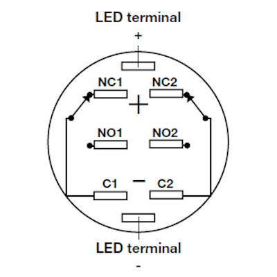
    Q: I looked through the wiring guide for the illum. switches on the store site, didn't
    quite get it, can someone help?
    A: Yes, someone most certainly can!
    It would help though if you told us if there is something specifically you did not
    understand, or if you don't know the basics of electronics yet.


    Q: Also I have concerns about the size of the hilt, if the electronics will fit inside to be
    exact.
    Please let me know what you think. (I chose the shorter type 2 choke)
    A: Since you will be doing no sound, you only need space for batteries and a resistor/buckpuck
    inside the main hilt section. With the resistor/buckpuck being the size of a lump of
    sugar, it will definately fit in there.


    Q: Oh and one more thing: What do you recommend for securing the batt. pack in the
    hilt?
    In the video tutorial it said use insulation, but I read in another post to use the
    speaker mount V2?
    What do you think?
    A: This i will leave to the other forum members who may have a more varied approach
    to this.


    Anyways, here's my list:

    - LED Blade Holder 4
    - MHS Choke 2 (there's my size concerns.)
    - Hilt Style 4
    - Pommel style 8
    - MPS Clip
    - MPS insert 12
    - P4 Electronics Kit
    - Service: Drill and Tap hole
    - Blue thumb screw

    - DPDT Yellow Illum. Ring Switch
    - AV Bezel
    - 220 ohm 1/4 resistor (that the right one?)

    - 26 gauge wire, red and black (if I use the illum. switch, should I get another colour too?)
    - Some 1/16" heatshrink

    I'm not quite sure about what blade I will use yet. I'd like to go with a medium long blade, I really hate the handling of the standard FX blade length, I'll think about that...

    Sorry for the long post, many questions, but I don't wanna mess up my first saber!

    Thanks for taking your time and helping out the newbs, this is great! *thumbs up*

    greetings from northern Germany,


    Stig
    I hope that answers some of your questions, and I
    also hope you don't mind me rearanging the text to something I personally
    find more pleasant to look at

    mTm


    Official Owner of Skottsaber at Bowling

  3. #3

    Default

    Thanks for your quick reply!

    No, of course I don't mind

    Although, I think you all know what I mean here, I'd still like to add that 'personal touch'.
    Since I'm going for a basic design, that gets a little difficult.
    So what I wanted to do is use a yellow ring Illuminated Switch.
    Q: I don't really have any experience, do you think that it's possible for me as a noob?
    A: Yes. If you can solder two wires together, and know the basics of electronics
    (the whole + and - thing) you should be able to wire it.
    Well, I do have a basic understanding of electronics. Very basic though It can all be solved with logic, of that I'm sure. And seing so many others constructing these amazing sabers,
    many wich you can really only call art, I feel rather confident that I can do it

    Looking at the Diagram on the site, the part I'm having problems with is... well the Illuminated switch part I just have no clue what cables to connect to what on the switch!
    Also, this may sound stupid, any advice on how to do the "t-part" where one wire goes straight onto another like it shows on the diagram (I'm sorry if I don't know the specific words, electronics hasn't been my interest until now, and I don't even know those words in German most likely. I guess I'd call it intersection in German, I hope that helps you understand what part I mean ) BTW: I'd like the switch to light up when I press it, while the blade is lit. I am just really confused with all the NO1 NC1 C1 C2 and so on. Is there any difference in wiring if I choose a momentary switch? Doesn't that mean it (the saber) only lights up while the switch is pressed?

    And does the led-switch dim the light of the saber itself a lot?

    Any help by someone who has installed such a switch would be awesome!

    Sorry for all the questions, I'm just becoming more and more confused...
    Thanks in advance,

    Stig

    EDIT: So I've looked through the tutorials again, I have to use the "guarded style switch hilt", right? Please don't get me wrong - I've been reading for days, I really just want to make sure I don't make any stupid mistakes
    Last edited by stig; 02-09-2011 at 08:10 PM.

  4. #4

    Default

    The "t-part" is a splice. It's not complicated to do, but sometimes holding the wires together while you're soldering them will make you frustrated. Trim the insulation off three pieces of wire, tin them, and then carefully solder each wire together, joining at the same intersection. After the solder joint is cooled, you will want to give it a slight tug to make sure the joint is secure. Then apply heat shrink to keep it safe.

    On the illuminated switch, you see 8 different terminals.


    C1, NO1, and NC1 work with each other. C2, NO2, and NC2 do the same. The C terminal is the common terminal that you should attach to one of the wires from your battery pack. The NO terminal is the Normally Open terminal that you should lead to your LEDs. You can ignore the NC terminal in this saber.

    The LED terminals marked + and - are for the LED in the switch. You will want to wire the switch LED in PARALLEL with your main LED. If you don't know the difference between series and parallel wiring, you will want to read a bit more, or check wikipedia. It explains far better than I can. On each leg of your parallel circuit, you will need to have an appropriate resistor for the LED on that leg. I don't know what kind of batteries you're using, so I can't help with which resistors to choose. There is a helpful resistor calculator on the store's site which I use, and it has most of the common options to select from.

    Don't worry, the LED in the switch won't dim your saber.

    I hope I didn't confuse you more, and good luck with your build!
    We all have to start somewhere. The journey is all the more impressive by our humble beginnings.

    http://led.linear1.org/1led.wiz for the lazy man's resistor calculator!
    http://forums.thecustomsabershop.com...e-to-Ohm-s-Law for getting resistor values the right way!

  5. #5

    Default

    Thanks for your reply!

    Well I'll be using the P4 Kit, so that'd be 6 V huh?
    You said I have to use two resistors. You mean for both (the one in the switch and the one lighting the blade) LEDs, not two resistors only for the switch, right?
    Well, I have a basic understanding of parallel wiring, seems I didn't sleep all through 6th grade!

    Thanks for your help, I still don't quite get it, but this sure cleared it up a bit! I'm getting there

    kind regards,


    Stig

  6. #6

    Default

    With the 4 AAA battery holder, you'll have 6V using regular alkaline batteries. You could choose to use AAA NiMH rechargeables instead, those would come out to 4.8V total.

    And you are correct, you will need one resistor for the switch LED, and another for the main LED.
    We all have to start somewhere. The journey is all the more impressive by our humble beginnings.

    http://led.linear1.org/1led.wiz for the lazy man's resistor calculator!
    http://forums.thecustomsabershop.com...e-to-Ohm-s-Law for getting resistor values the right way!

  7. #7

    Default

    Okay! Another noob question: If I have a resistor installed for the Switch-LED, isn't the voltage then too low for the main LED? Wait, isn't this where the parallel wiring does it's part... Interesting! I shall do some more research


    Thanks! Got me a little closer again


    Stig

  8. #8
    Sith Adept dgdve's Avatar
    Join Date
    Aug 2009
    Location
    Virginia (near DC)
    Posts
    647

    Default

    Heya Welcome,

    I can tell your really jumping in head first.. there's only one piece of advice I can offer to you... take it slowly.. maybe read through a few of the stickies before you tackle it.. then be patient.. some things are so easy once you have the parts in hand but so confusing on paper(like recharge ports).. My advice.. dont order anything not one piece until you have your wiring all figured out.

    Now to answer your question you will indeed be running a parallel/(its own wires) circuit for the switch LED with the resistor (doesnt matter which leg, but I keep switchs on pos+ and resistors on neg- sides). I hope that helps

    EDIT!: you know you can use a "dummy" cell to drop the voltage from 6v to 4.5v(on standard batteries) out of the battery pack, that will allow you to shrink the size of resistors you need
    Last edited by dgdve; 02-10-2011 at 07:56 AM.
    Quote Originally Posted by Gin Malinko View Post
    just an added note on this.
    I vote dgdve as the site's motivational speaker. haha
    "Yes Lord Vader, and I too have a gift... for you.."


    "There is no good or evil, no black or white.. There is only.. Perspective"

  9. #9
    Board Lurker tankhog's Avatar
    Join Date
    Aug 2010
    Location
    Edmonton, Alberta
    Posts
    34

    Default

    As I've been eyeballing getting myself an illuminated switch also I'll throw in my two cents -

    As he's running just the led ( no soundboard or driver) doesn't he need just a spst switch instead of the dpdt?
    Silver serpent's post above about wiring the switch up but ignoring the normally closed terminals,
    What effect would that have? Having to press the switch either twice to activate or twice to deactivate?

    My understanding of using the dpdt switches (especially with running a board or driver) is that people usually use a separate power supply for the LED and then a separate power supply for the board, hence needing the two 'on positions' in the one switch...

    But then again I could be out to lunch as I have zero exp with the illuminated switches!

  10. #10
    Council Member
    Jedi Council Member
    Jedi-Loreen's Avatar
    Join Date
    Dec 2005
    Location
    Not of this Earth
    Posts
    6,077

    Default

    Yes, from what we know of what he's using, so far, he only needs a SPST switch, but if he wants an illuminated one, the Store only has them in DPDT form.

    You can wire your switch to use the NO and C terminals. In this configuration, your switch button would be depressed when off, then up when you turn it on. I believe Jay-gon does his switches that way now because he likes the look of the button being
    up when the saber is turned on better than when it's depressed.

    2 power supplies are not usually needed, but, depending on the current output of the sound board, some people want/need to directly drive, or use a buck puck for their LED on one circuit of the switch, and power the sound board on another.
    In order to see the Light,
    you must sometimes risk the Dark.
    TCSS MODERATOR


    BLUE 8 Ready to ROCK and ROLL!

Bookmarks

Posting Permissions

  • You may not post new threads
  • You may not post replies
  • You may not post attachments
  • You may not edit your posts
  •