And that's probably why I've never seen anyone put a recharge port there before.


And that's probably why I've never seen anyone put a recharge port there before.
In order to see the Light,
you must sometimes risk the Dark.
TCSS MODERATOR
BLUE 8 Ready to ROCK and ROLL!

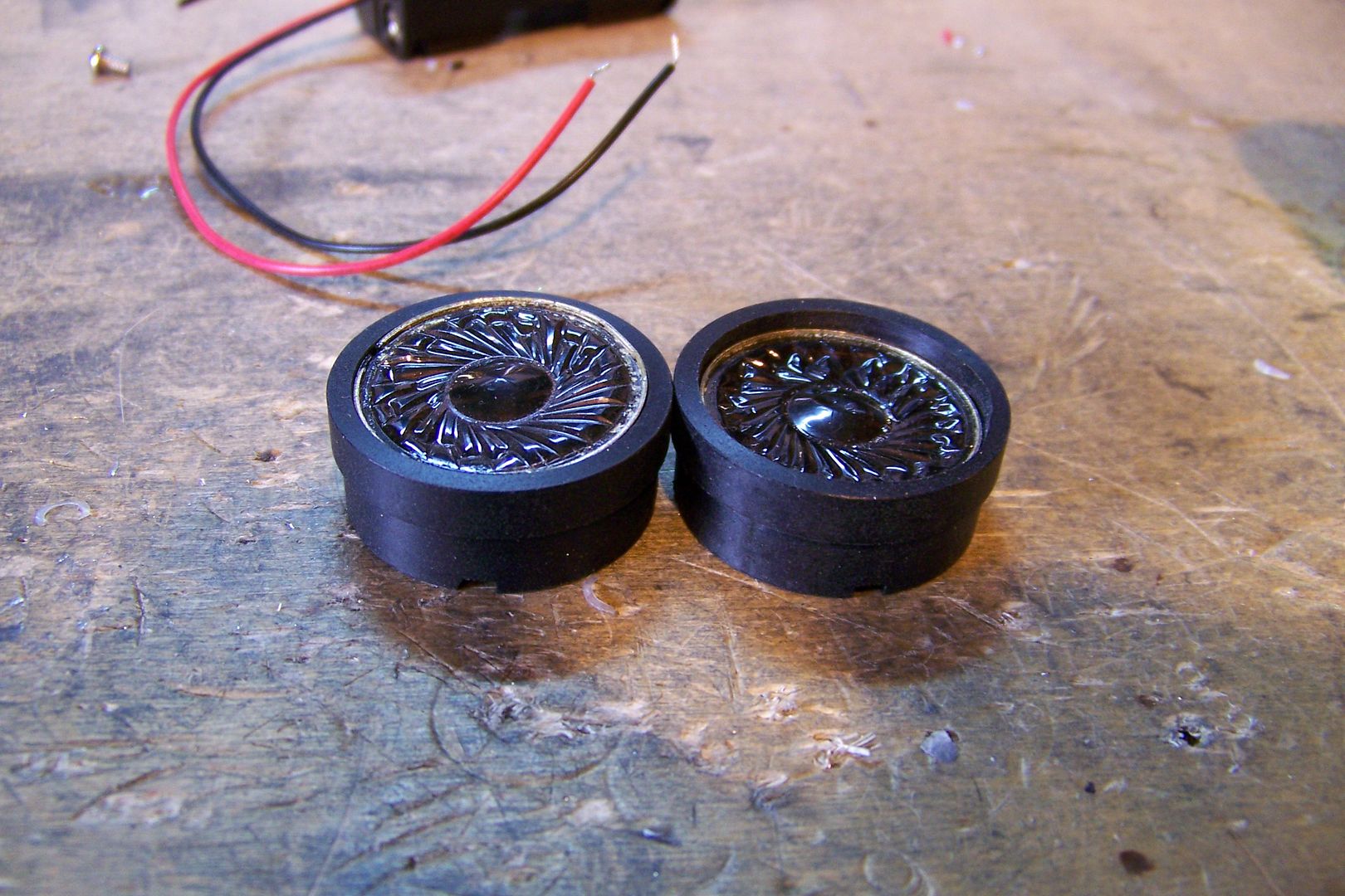
I'm not sure if I have anything posted here about that, but here's an excerpt from my build for Brass Saber 21 that shows how I modified a TCSS speaker mount v2 for wiring for getting wires around a speaker for an accent led (a it should also work for a recharge port, too, except you'll need to make channels for three wires instead of two):Originally Posted by Bothrops

I don't think the first modification to recess the speaker will be necessary, since the speaker mount has been redesigned since I wrote that, but I think overall, it should work and allow you to put the recharge in the pommel insert....I would heed Ace's advice about wires twisting when you try to attach the pommel with the recharge port in the side of it.....that usually results in broken wires.To be able to wire the led for the pommel to light up, I'm going to need to be able to get wires around the speaker in a way that keeps them from getting squashed and subsequently damaged by the pommel. I decided that I could do this by increasing the depth of the "step" that the speaker sits on in the speaker mount:
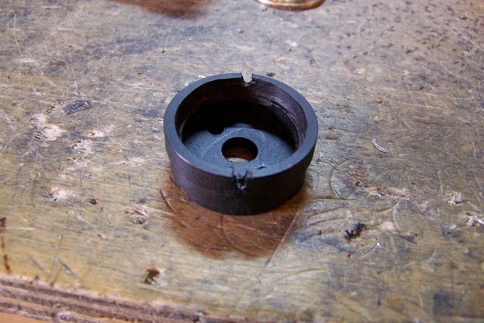
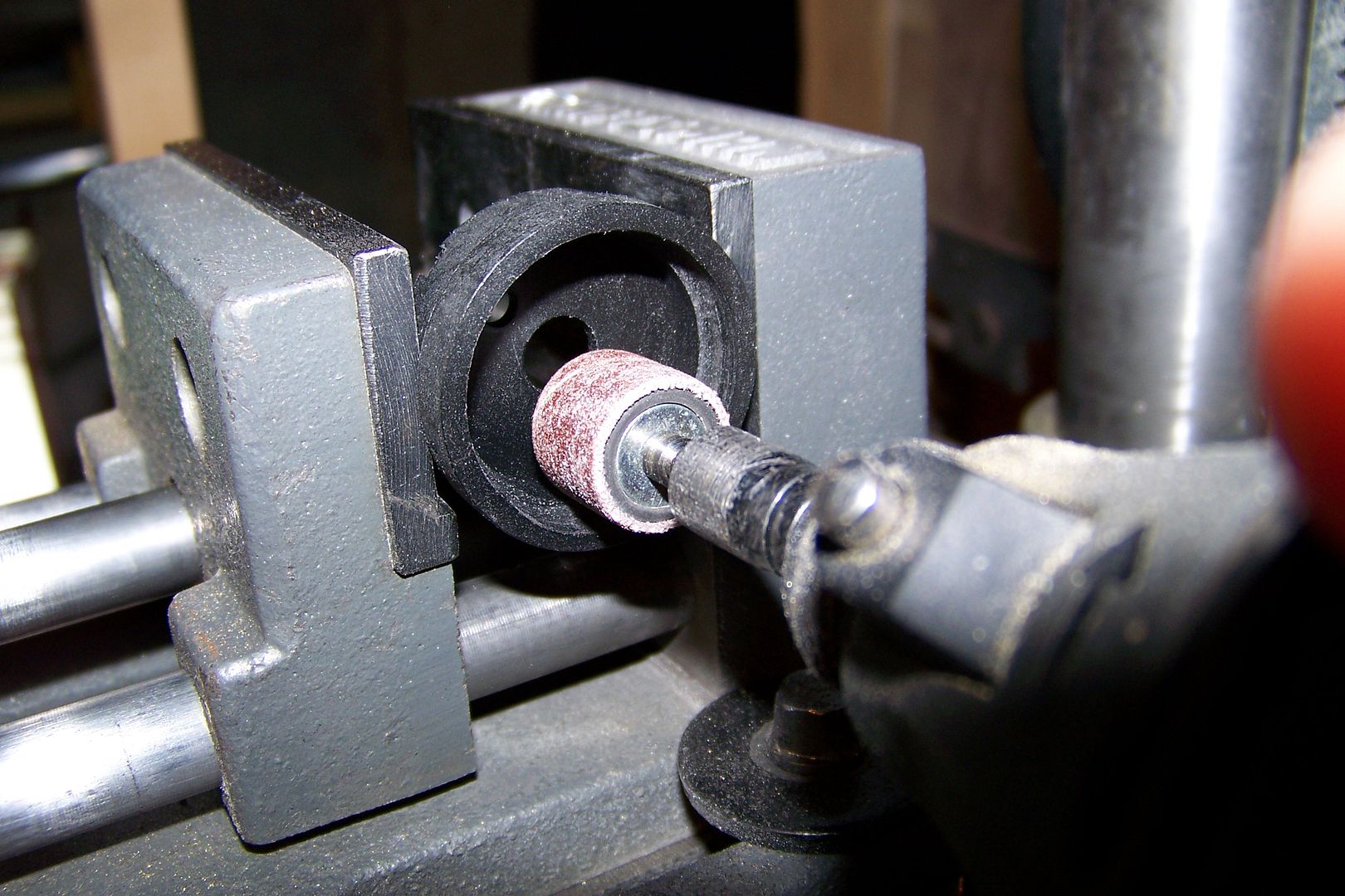
Since I don't have a lathe, I'll do this the cheap way...I'll use the sanding drum attachment on my rotary tool instead.
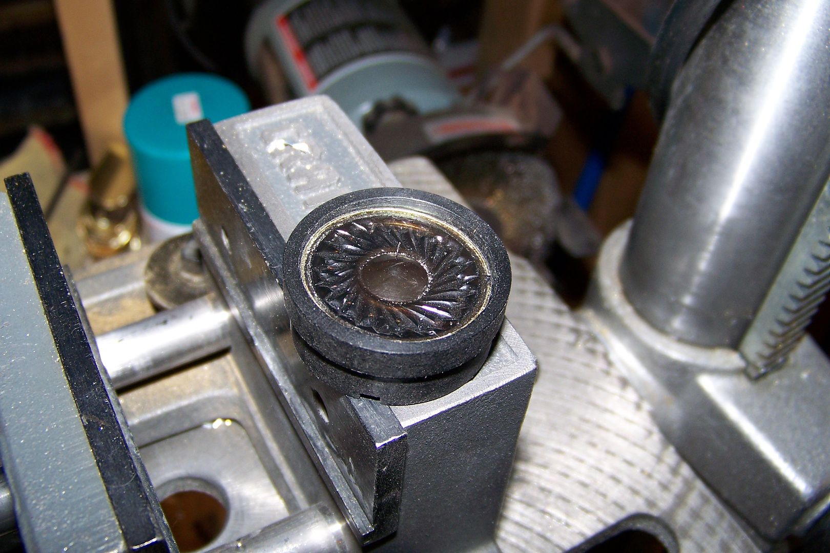
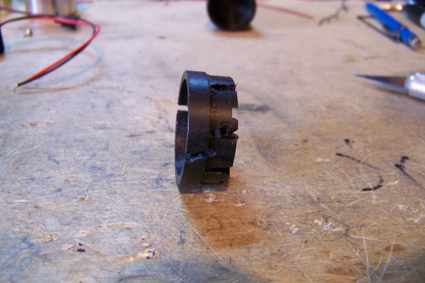
After a few minutes of grinding, I had increased the depth to an acceptable level:
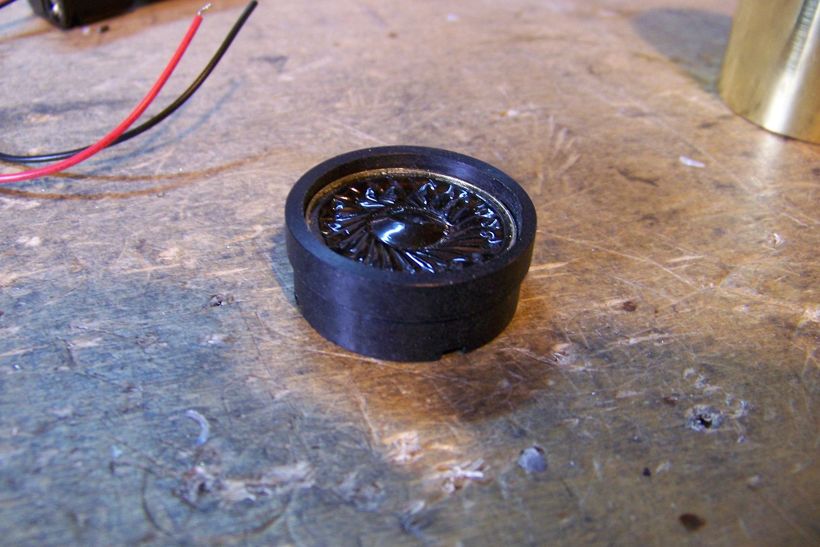
Here it it next to an original speaker mount:
Now I'll need to cut some channels for the wires. I'll use a side scrolling tungsten carbide bit for that:
Hmm...those need to be deeper, I think:
That should work....let's try a piece of wire in there and see how it looks:

Yeah, I think this should do the trick!
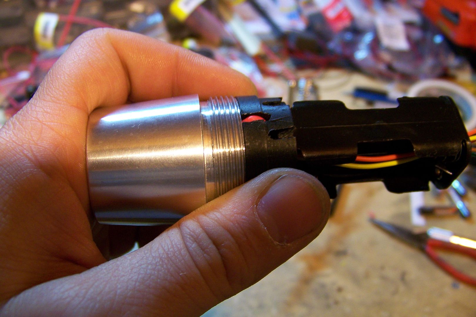
Let's try it against a pommel:
Yup! That's definitely going to work. The wire was tucked in nicely inside the speaker mount and shouldn't be a problem when installing the pommel after changing the batteries.
Now, since I'm cutting and grinding on this speaker mount anyway, I might as well go ahead and do the modifications to back vent it, too:
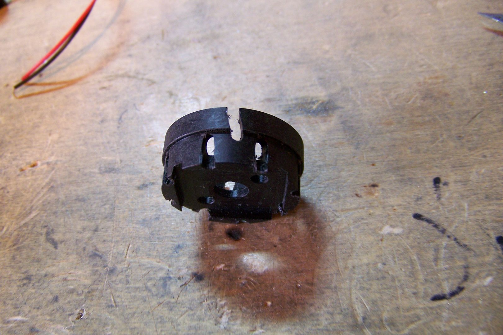
I used the same tungsten carbide side scrolling cutting bit that I used earlier to "mill" some channels for the sound waves to vent through. This should change the pitch and tone of the saber making it seem louder than it really is.
I'll attach this to the battery holder using two 4-4 screws that have been cut down so as not to contact the batteries or the springs in the pack and cause a short:
I think I can get started on wiring this one up!
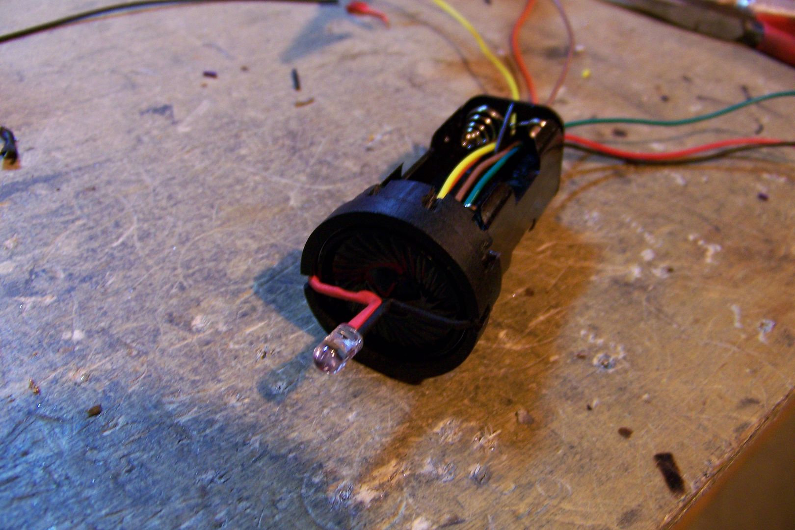
To start on the wiring, I'll need to run wires through the battery pack to the speaker and the accent led for the pommel:
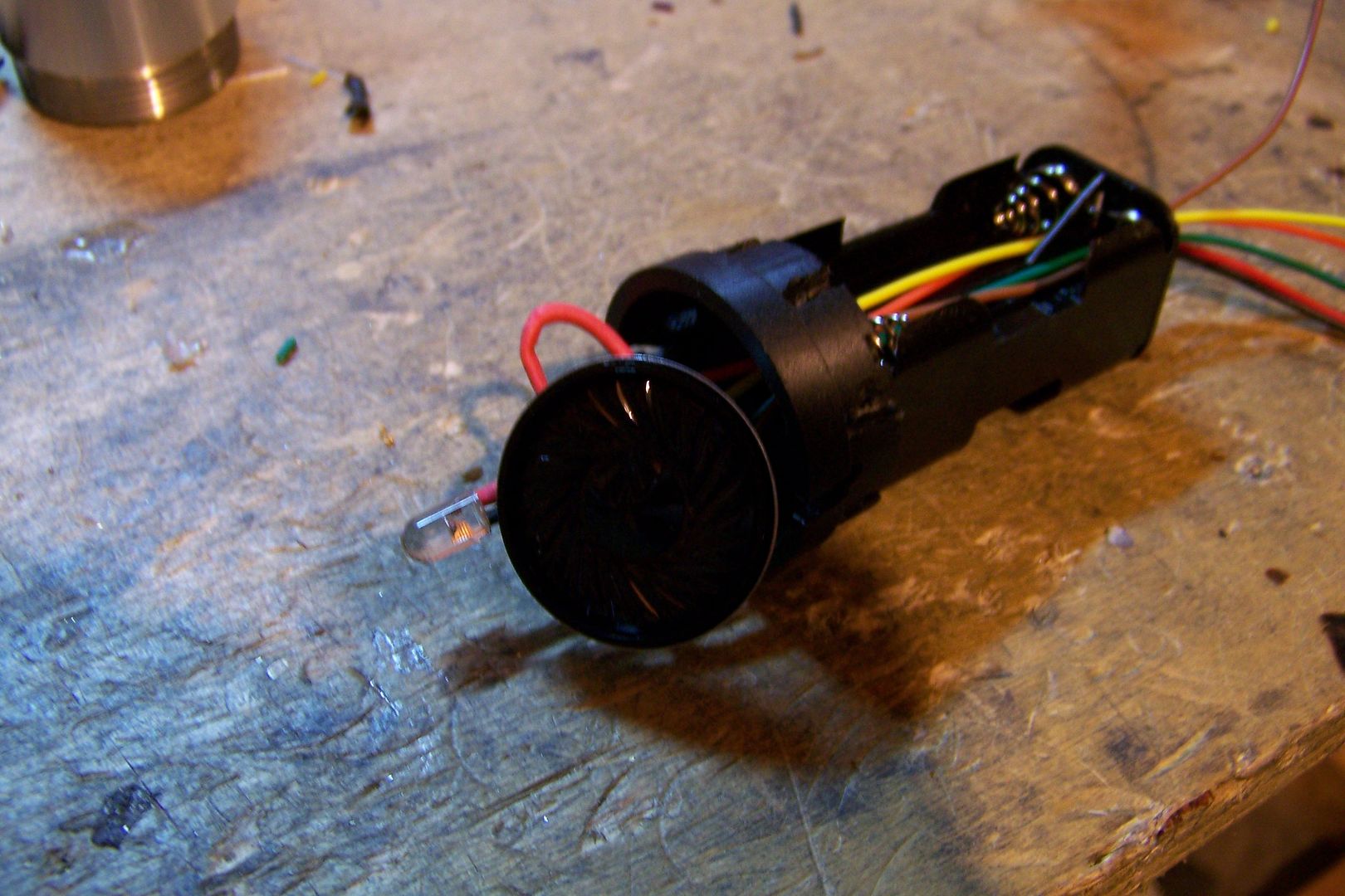
The led used here is a 5mm white, 3.3v, 20ma. and will require a resistor. I'll add that at the soundboard, though.
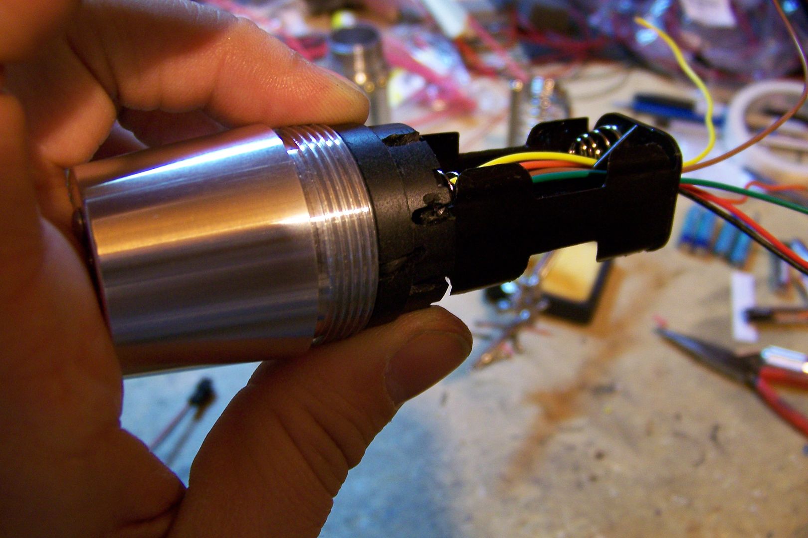
This assembly will fit against the pommel like so:
The wires for the led are nicely tucked in and out of the way.
I applied some power to the led using the 2-AA battery holder and checked to see how it lit the crystal:
That looks good!
Got a question? Start Here. Have you tried the Thread Index yet? Most questions can be answered there.


I thought of that last night, and I think I have a way around that. Since the main body is a sink tube, the pommel is screwed to the MHS to 1.5" sink tube adapter and sled into the sink tube. The Covertec knob will be screw into both acting as a set screw.
Ah. So you can just screw the adapter onto the pommel and slide it into the sink tube. That should work.
In order to see the Light,
you must sometimes risk the Dark.
TCSS MODERATOR
BLUE 8 Ready to ROCK and ROLL!
 Posting Permissions


 Reply With Quote
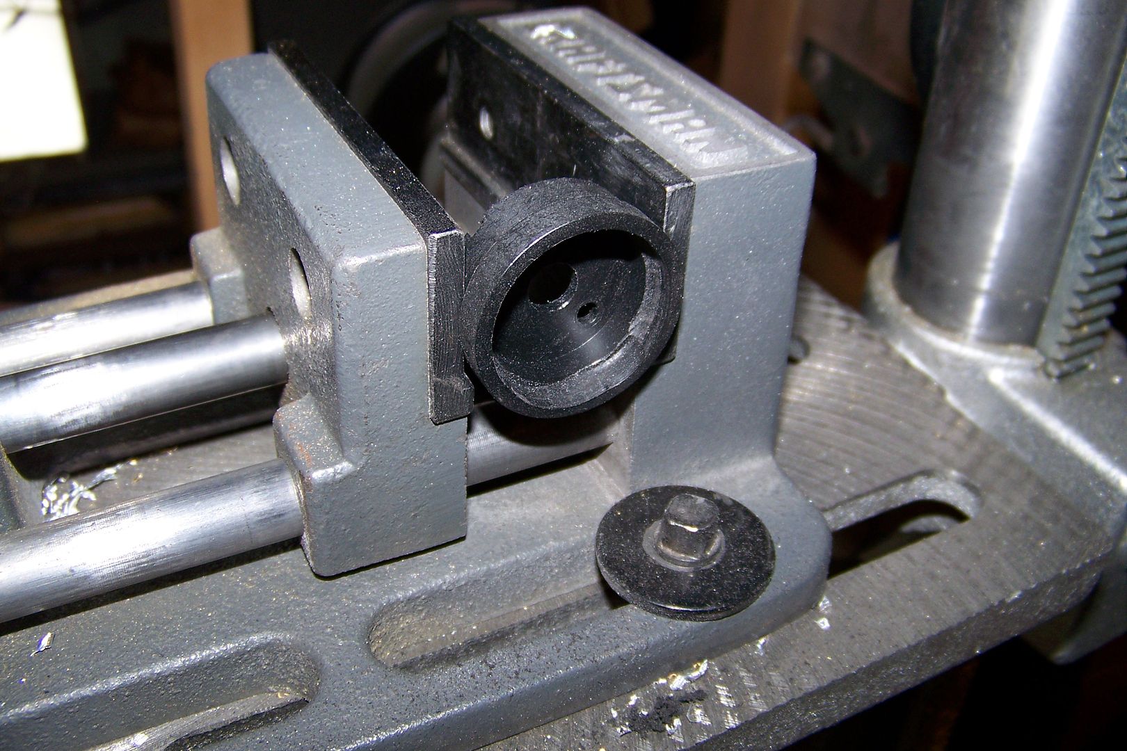


Bookmarks