Page 1 of 4 1 2 3 ... LastLast
Results 1 to 10 of 32

Thread: Jay-gon Jinn's MHS Mara Jade(ish) build (MHS, Petit Crouton, 7.4v Li-Ion, AV switch)

  1. #1

    Default Jay-gon Jinn's MHS Mara Jade(ish) build (MHS, Petit Crouton, 7.4v Li-Ion, AV switch)

    This saber is being built for a friend of ine in the rebel Legion that is putting together a Mara Jade emperor's hand costume and is based on the Mara Jade hilt as seen on the "Decipher" card game card, and the version sold at Parks Sabers. It won't be an exact replica, but should be similar in appearance.

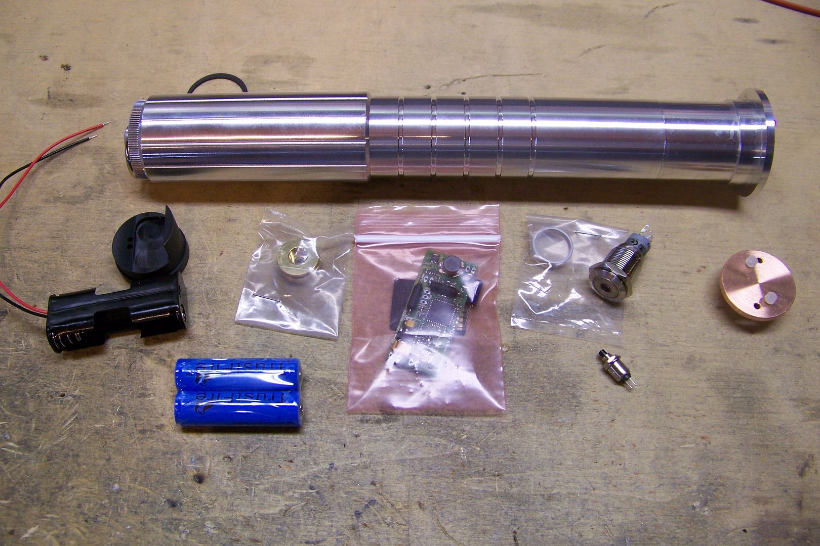
    Here's the basic parts this will be made from:

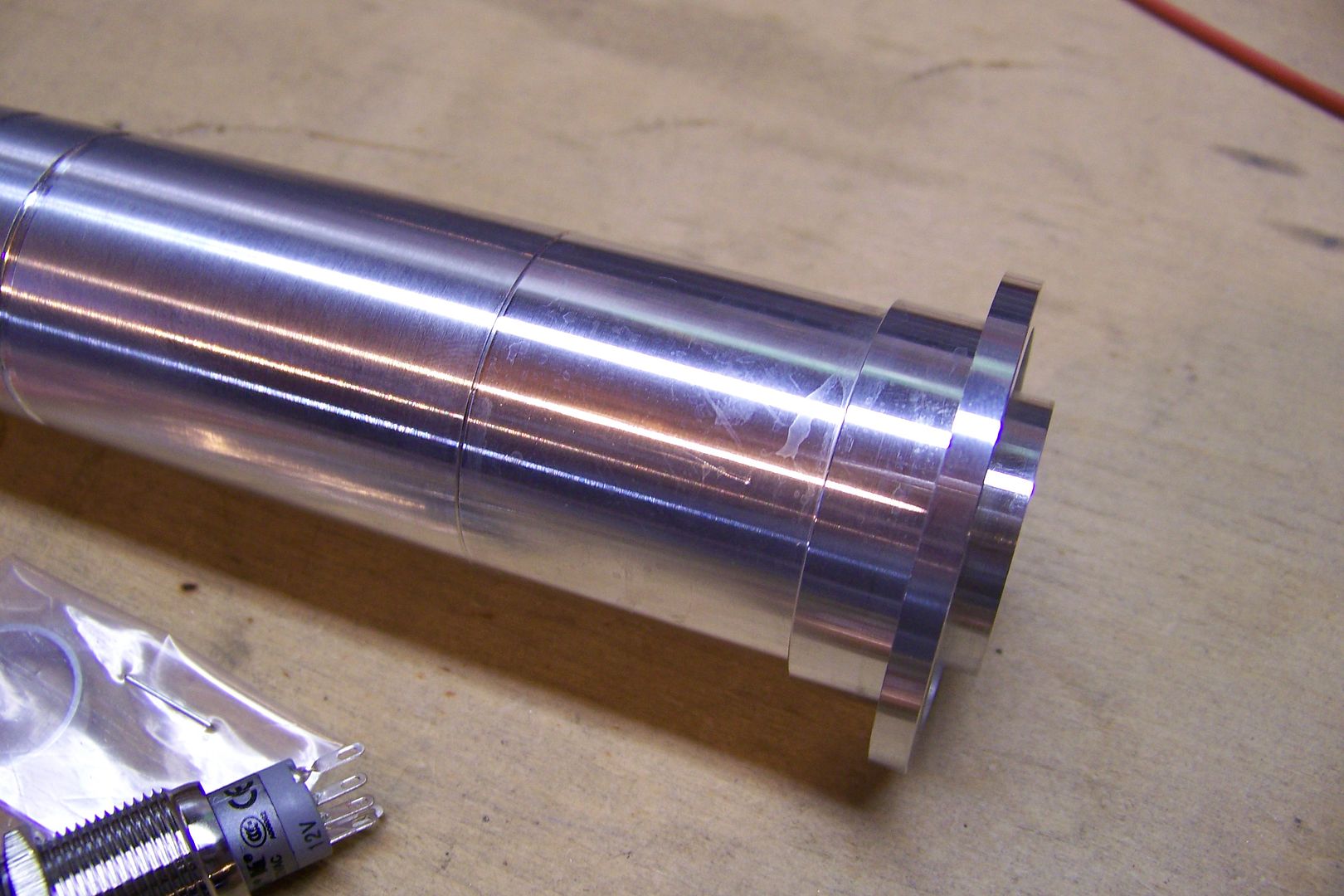
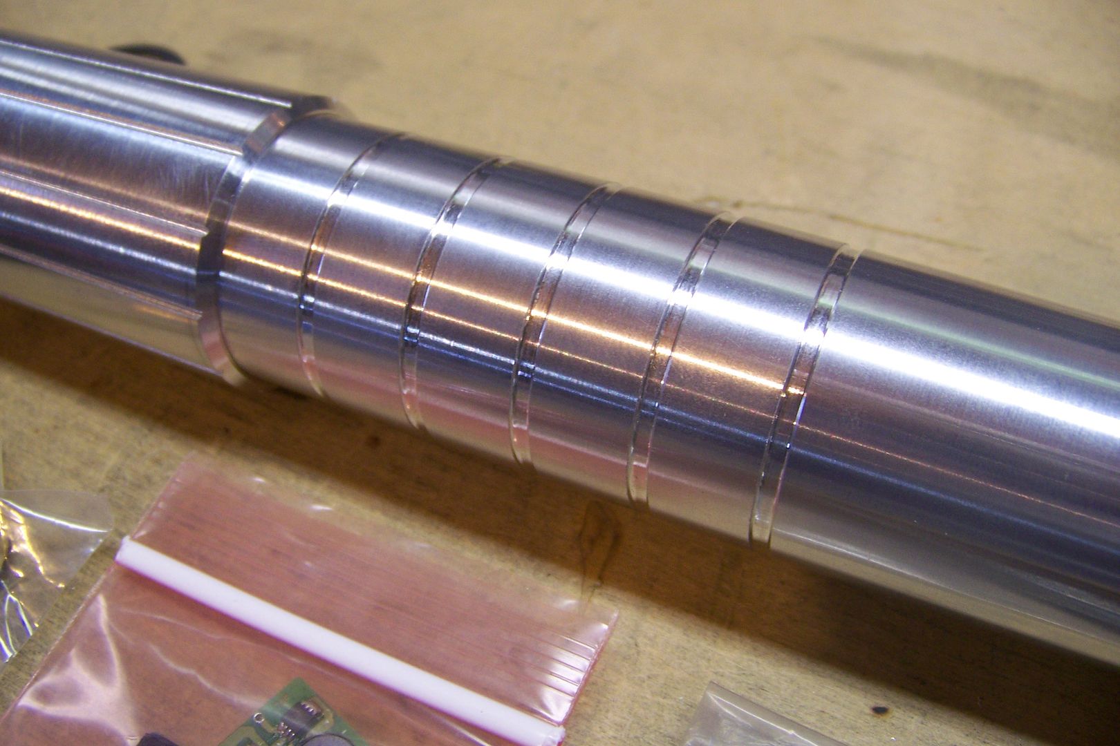
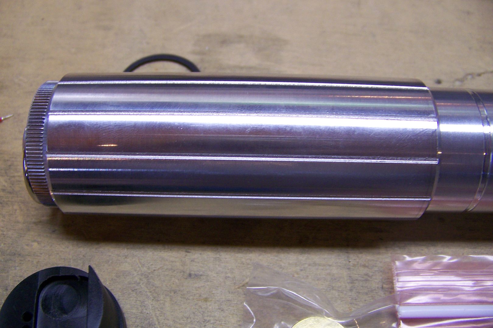
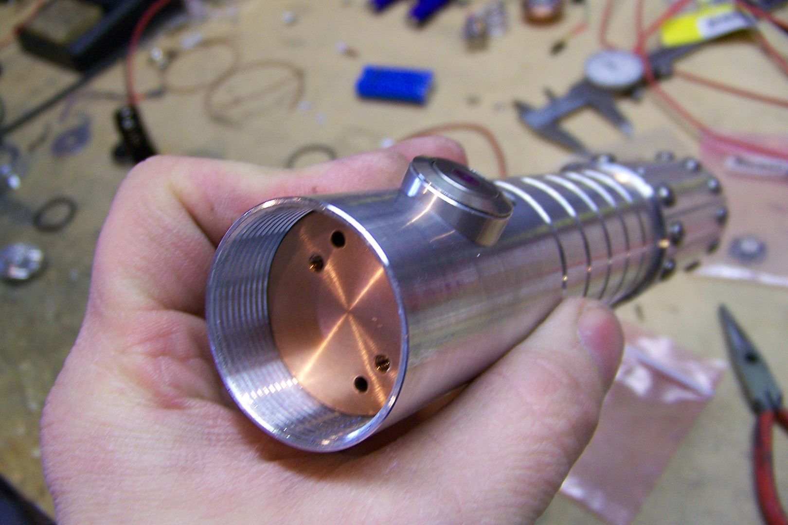
    MHS blade holder style 15, a 9" double female threaded connector with custom machined grooves, a pommel style 9 w/mpsi style 12.


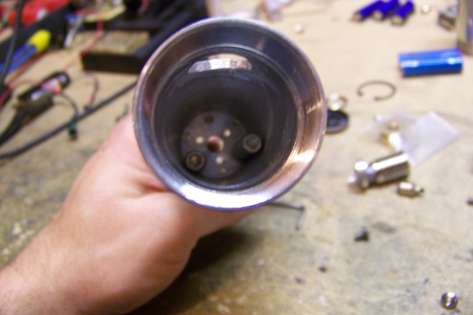
    The emitter/blade holder....I have the correct t-grip material to add to this later...that will likely be the last thing I do on it.


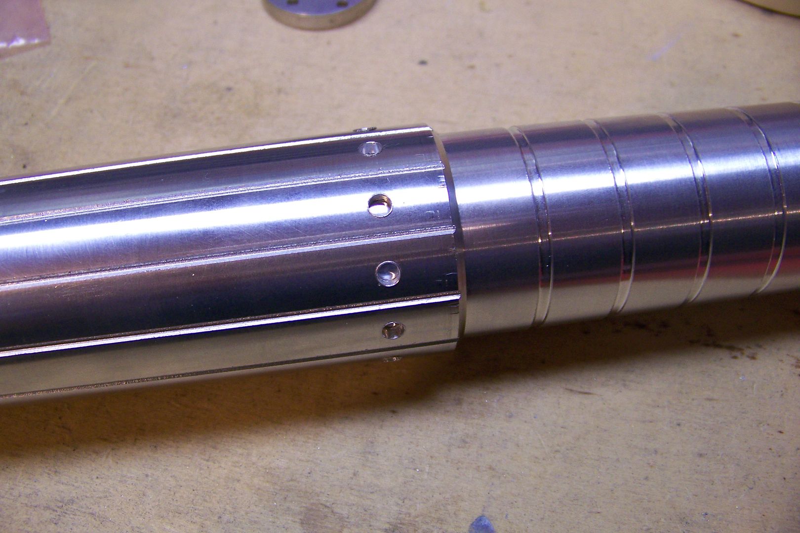
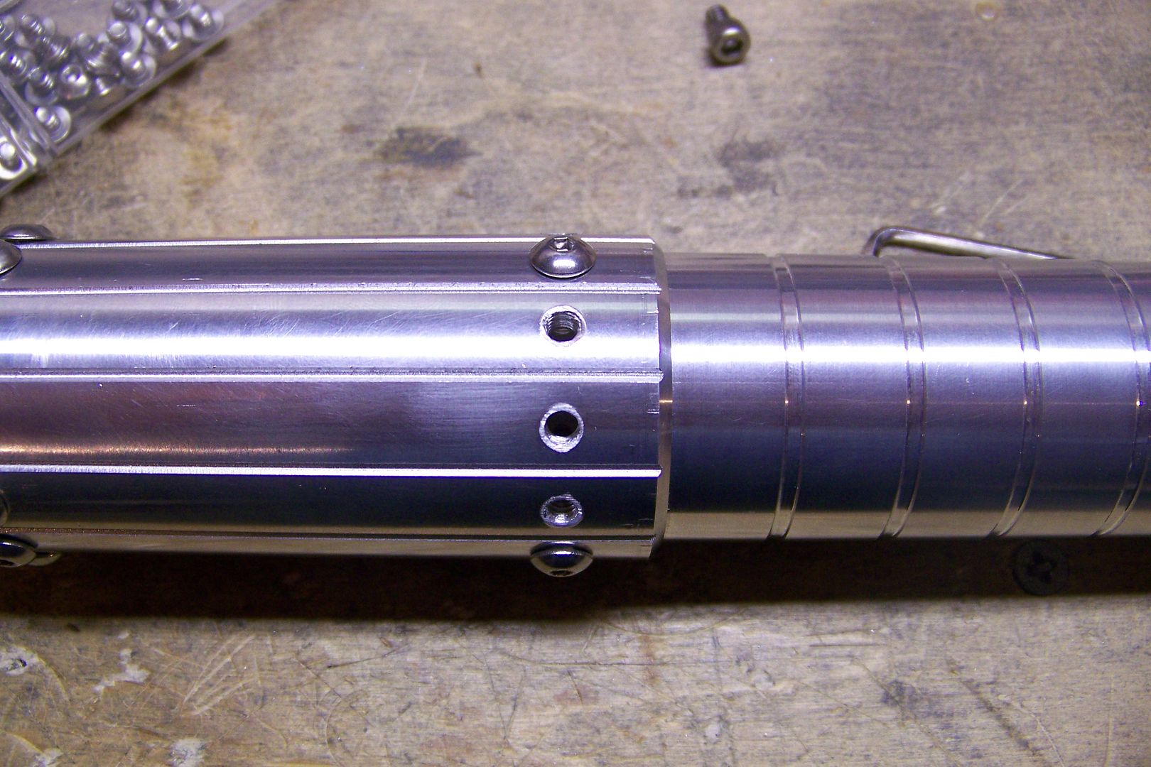
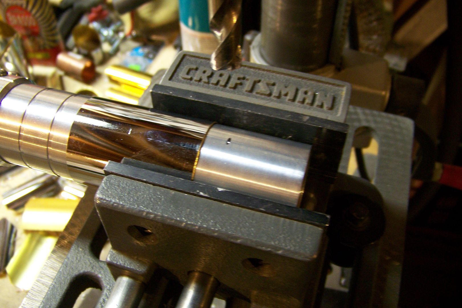
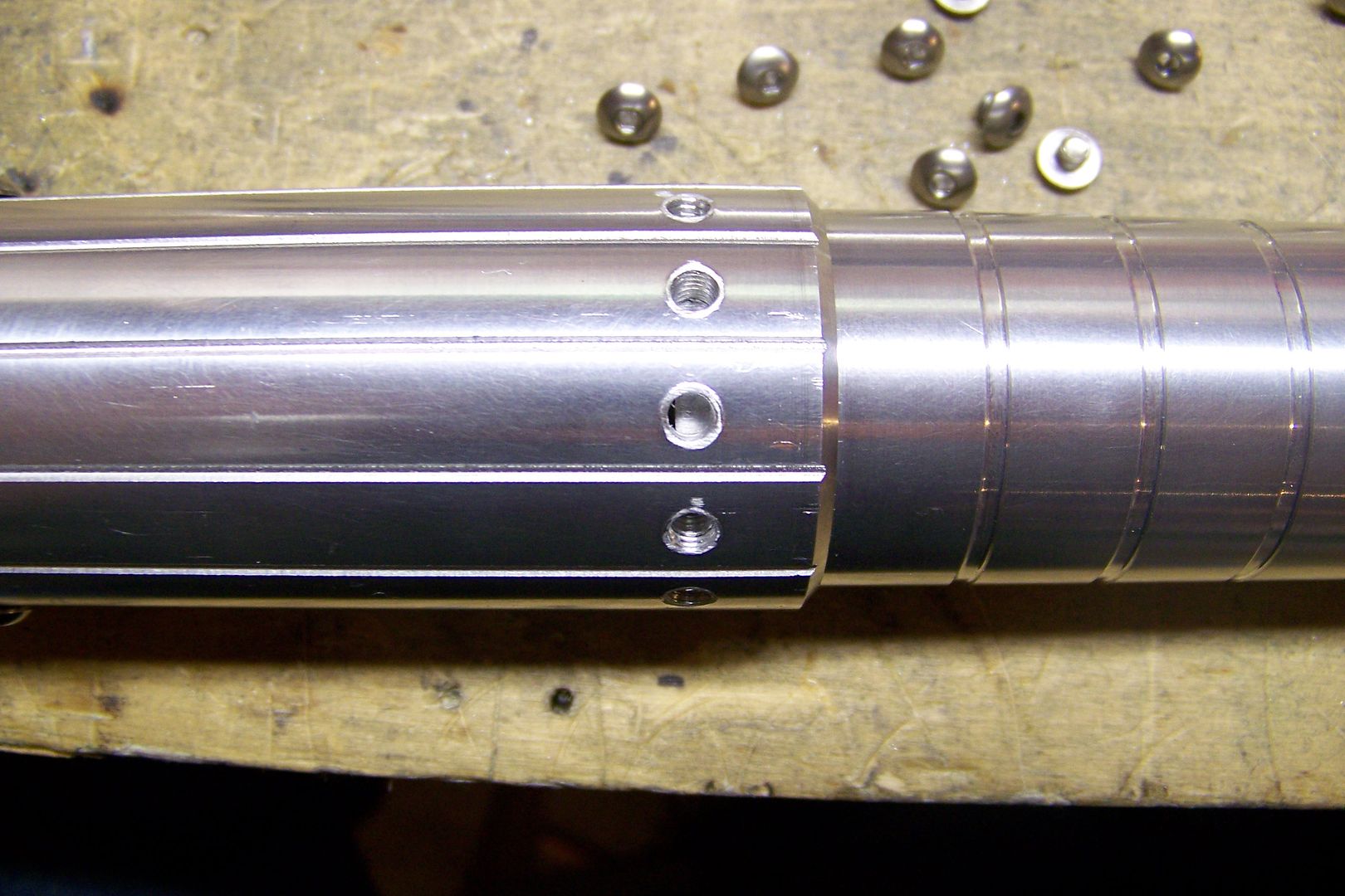
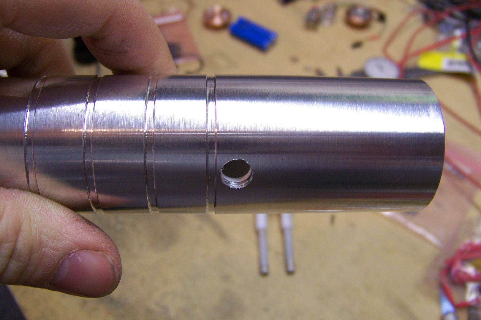
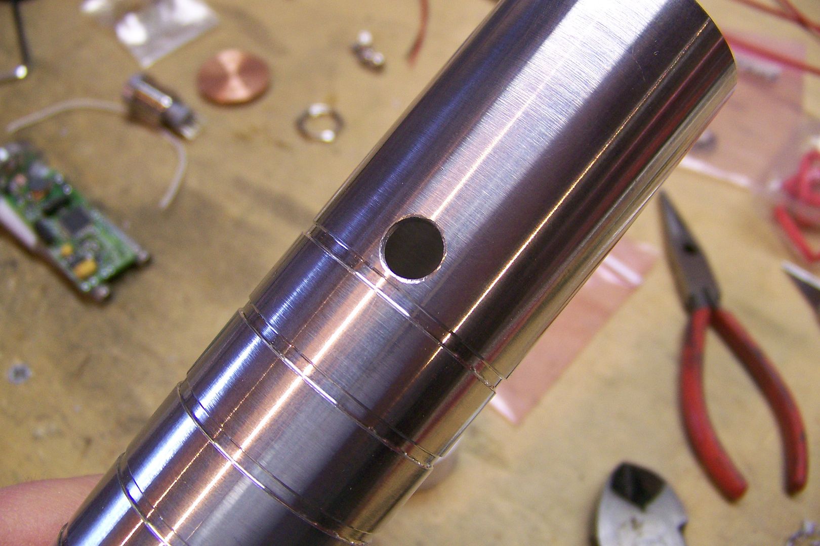
    The custom machined grooves on the 9" MHS double female threaded connector....Tim did a great job on that as usual!


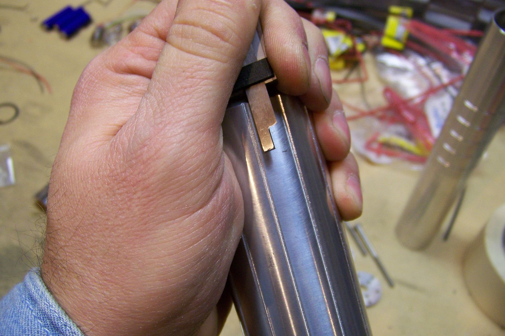
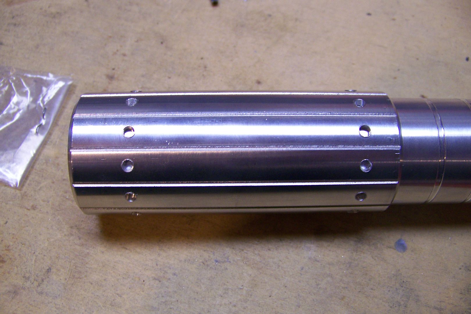
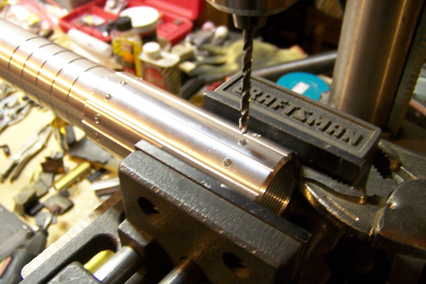
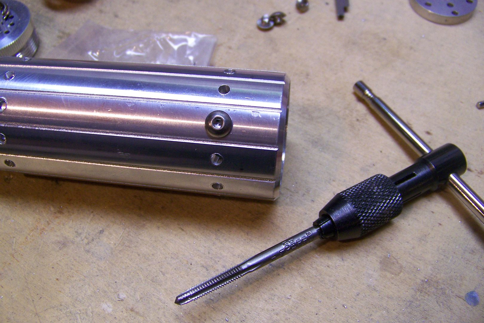
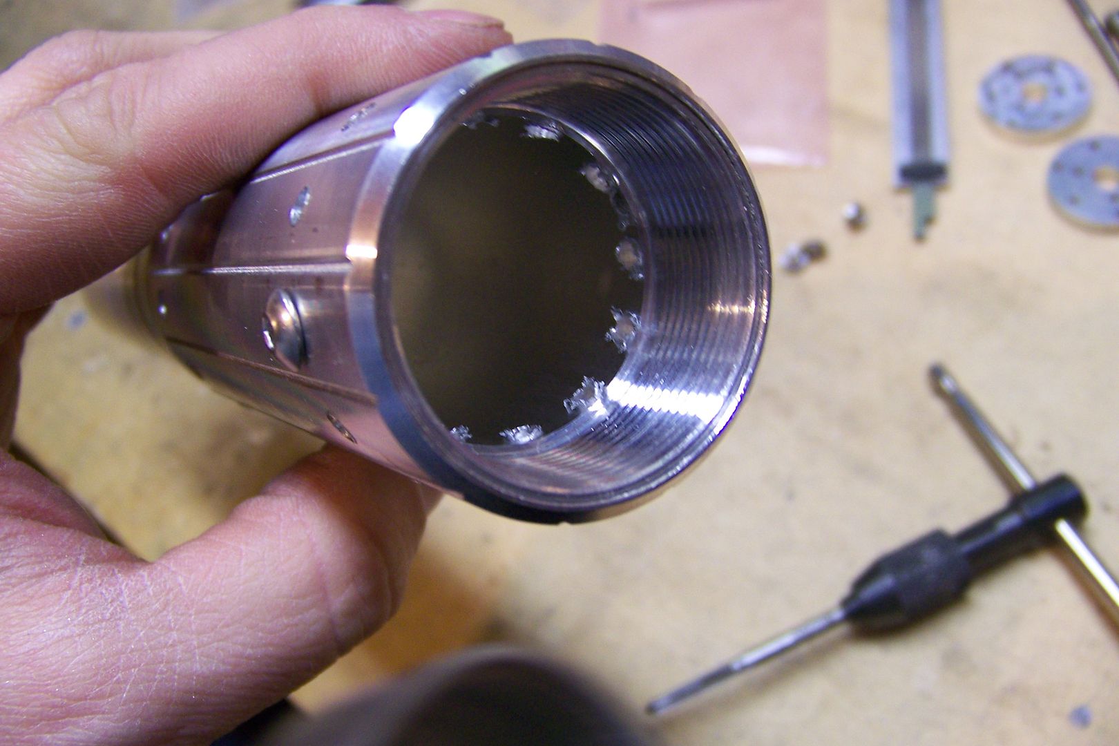
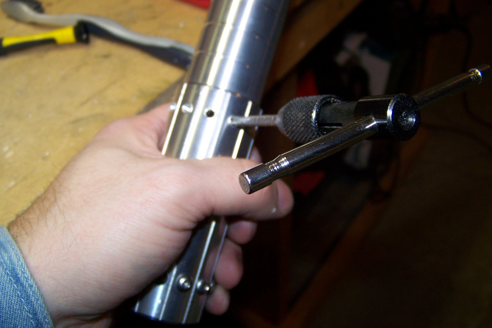
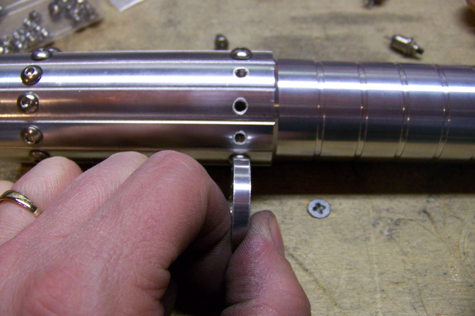
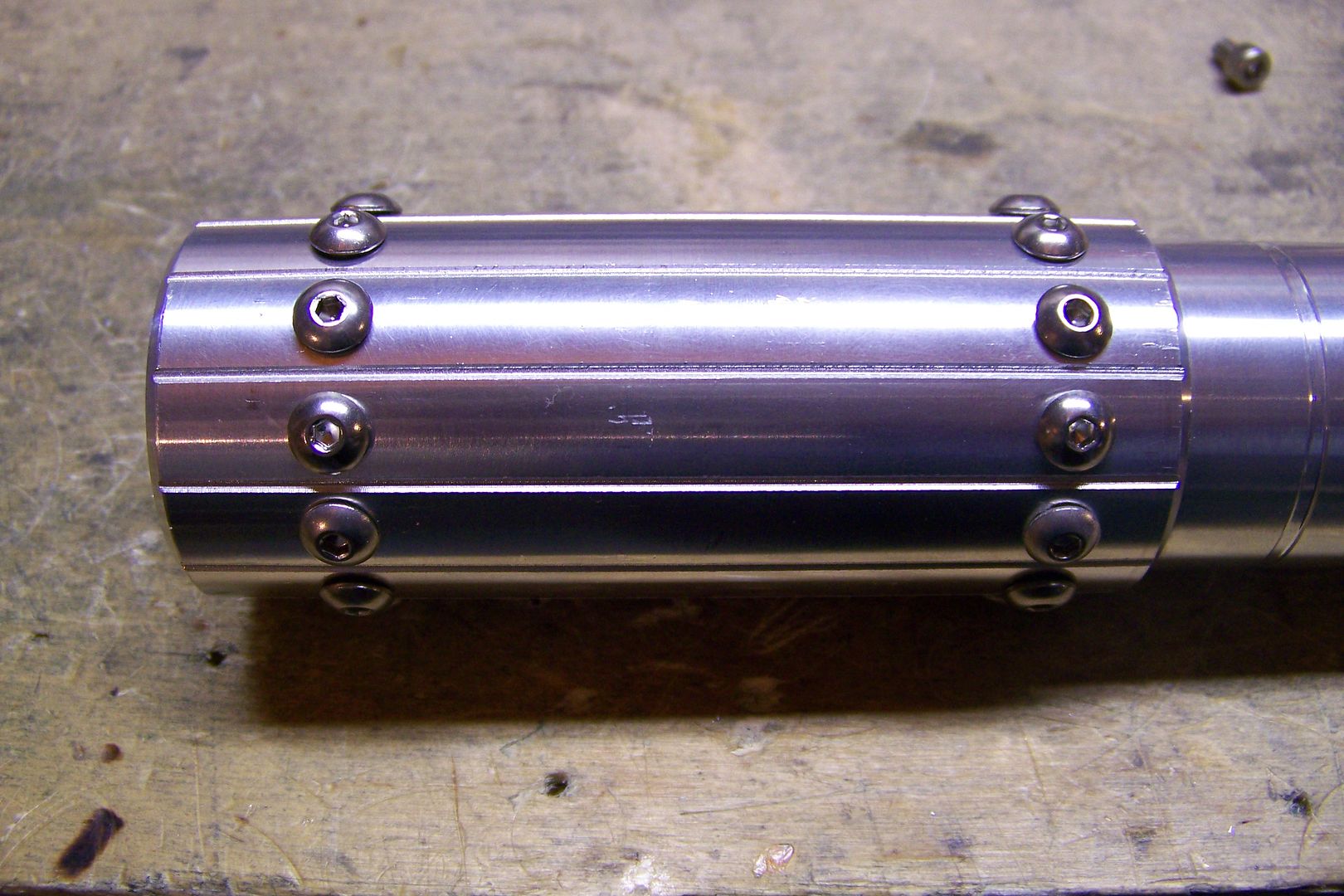
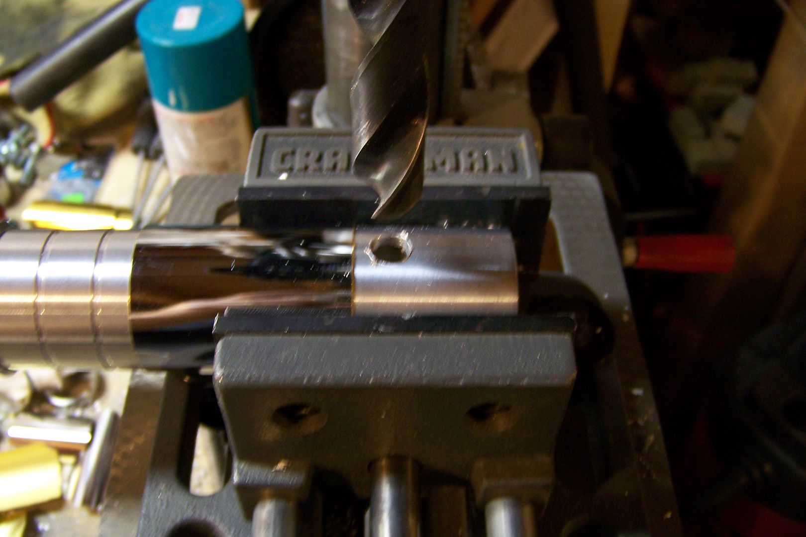
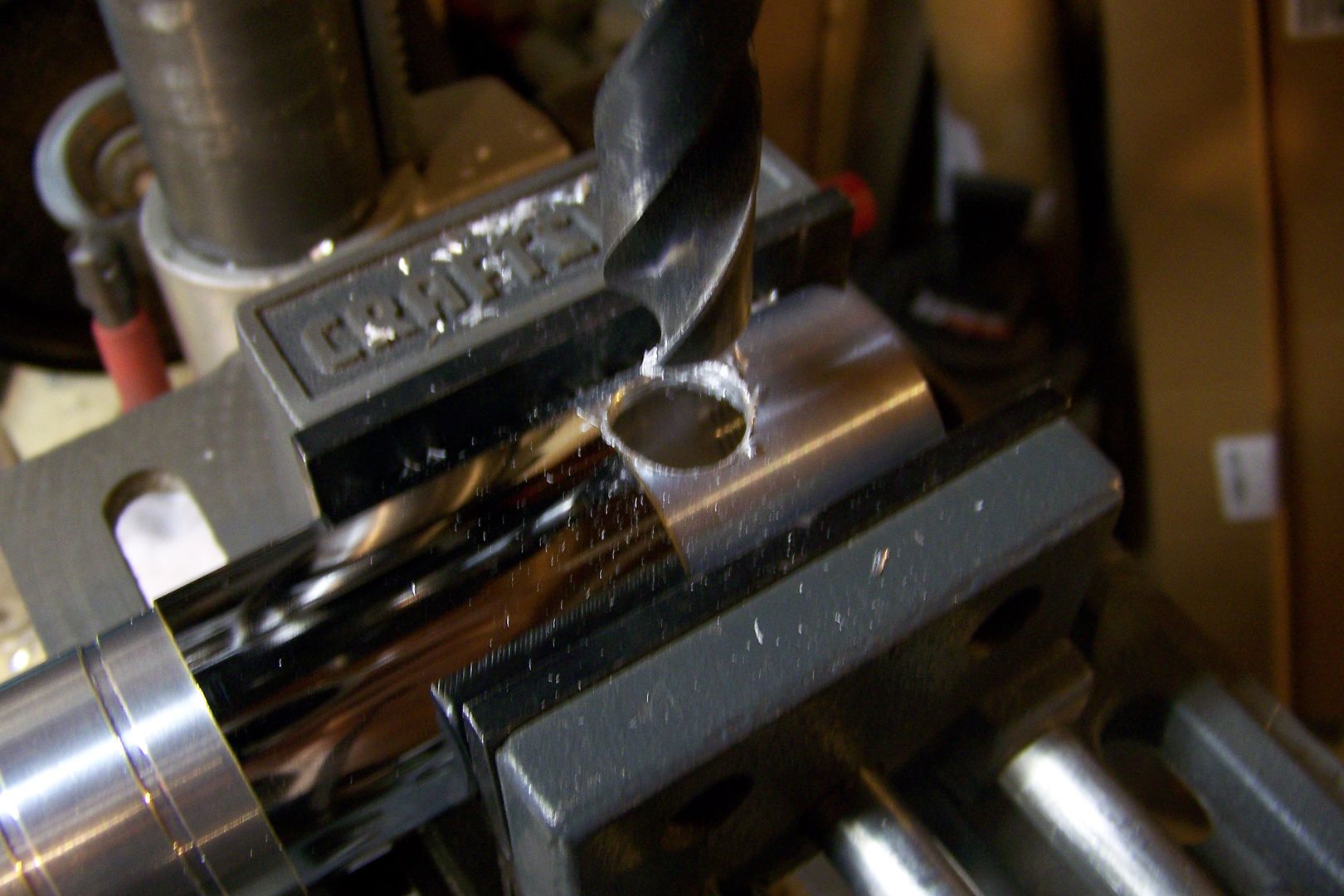
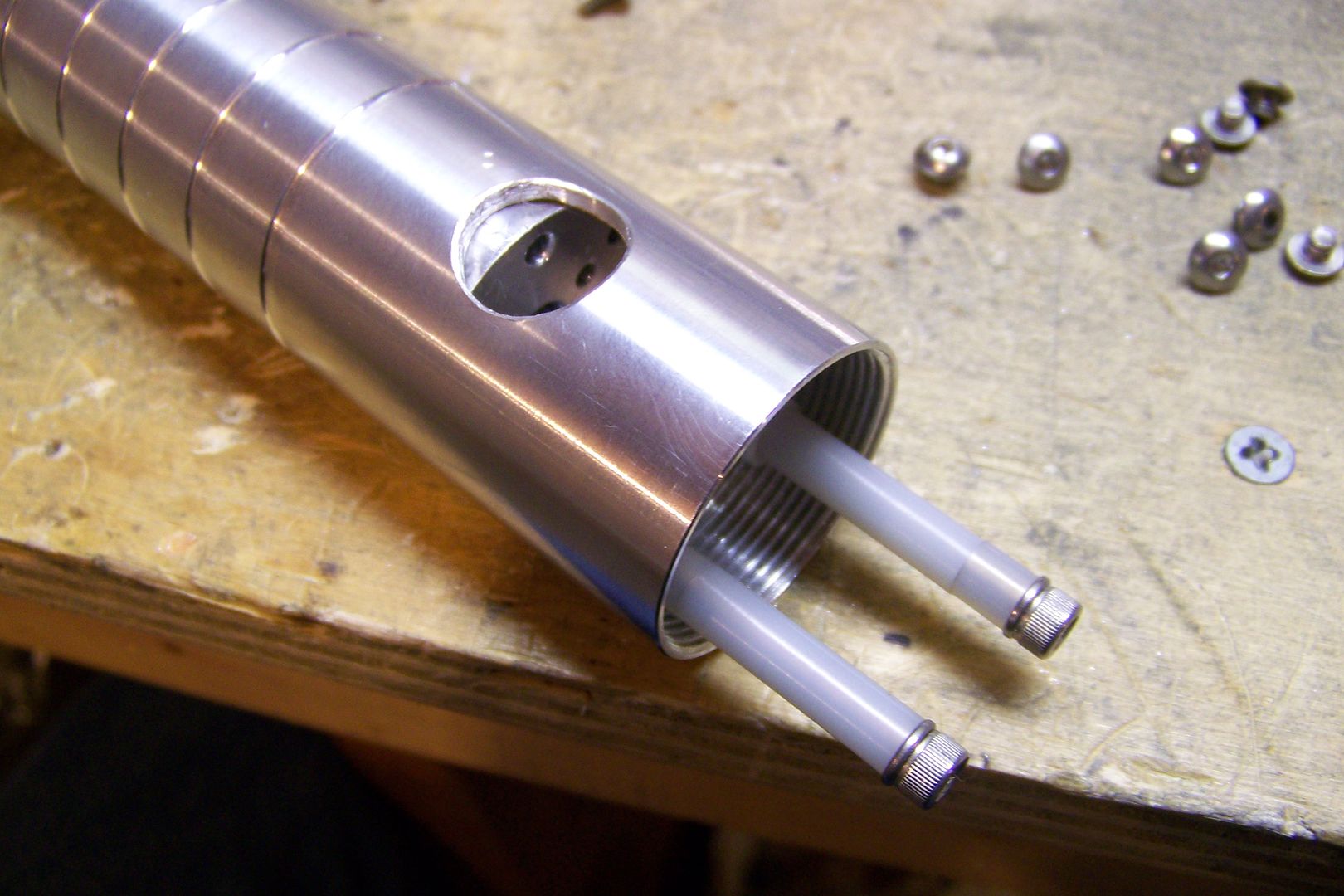
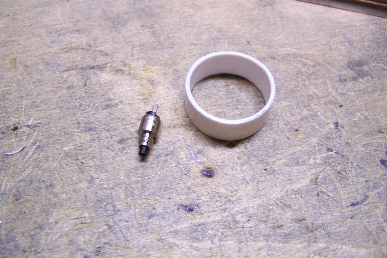
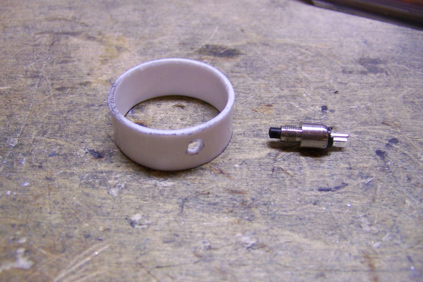
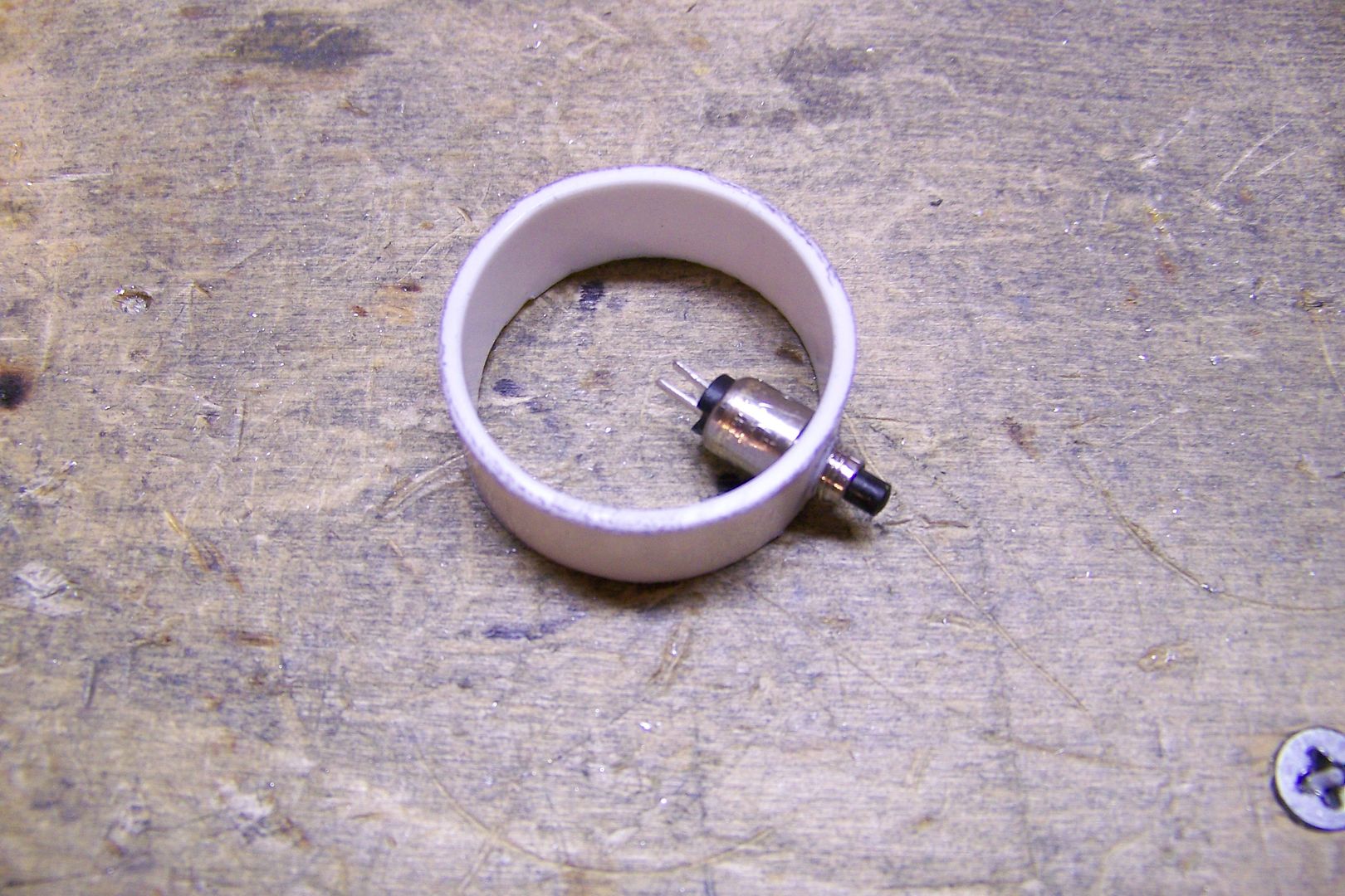
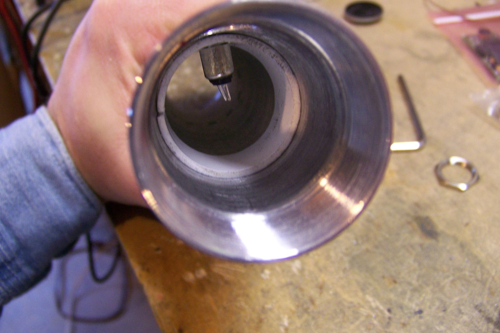
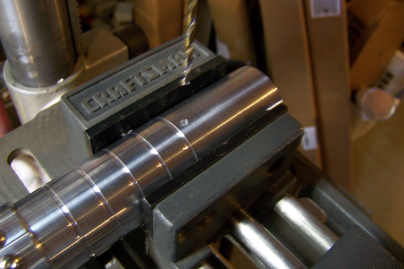
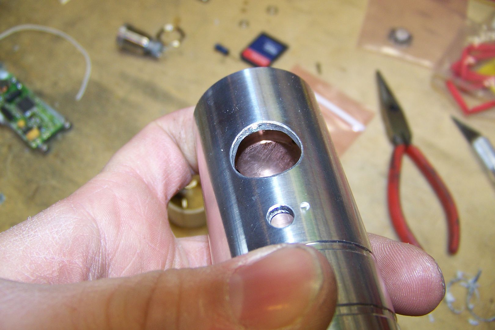
    The rear grip sleeve.....I'll have to drill and tap this for 24 button head screws....that'll be fun, I'm sure


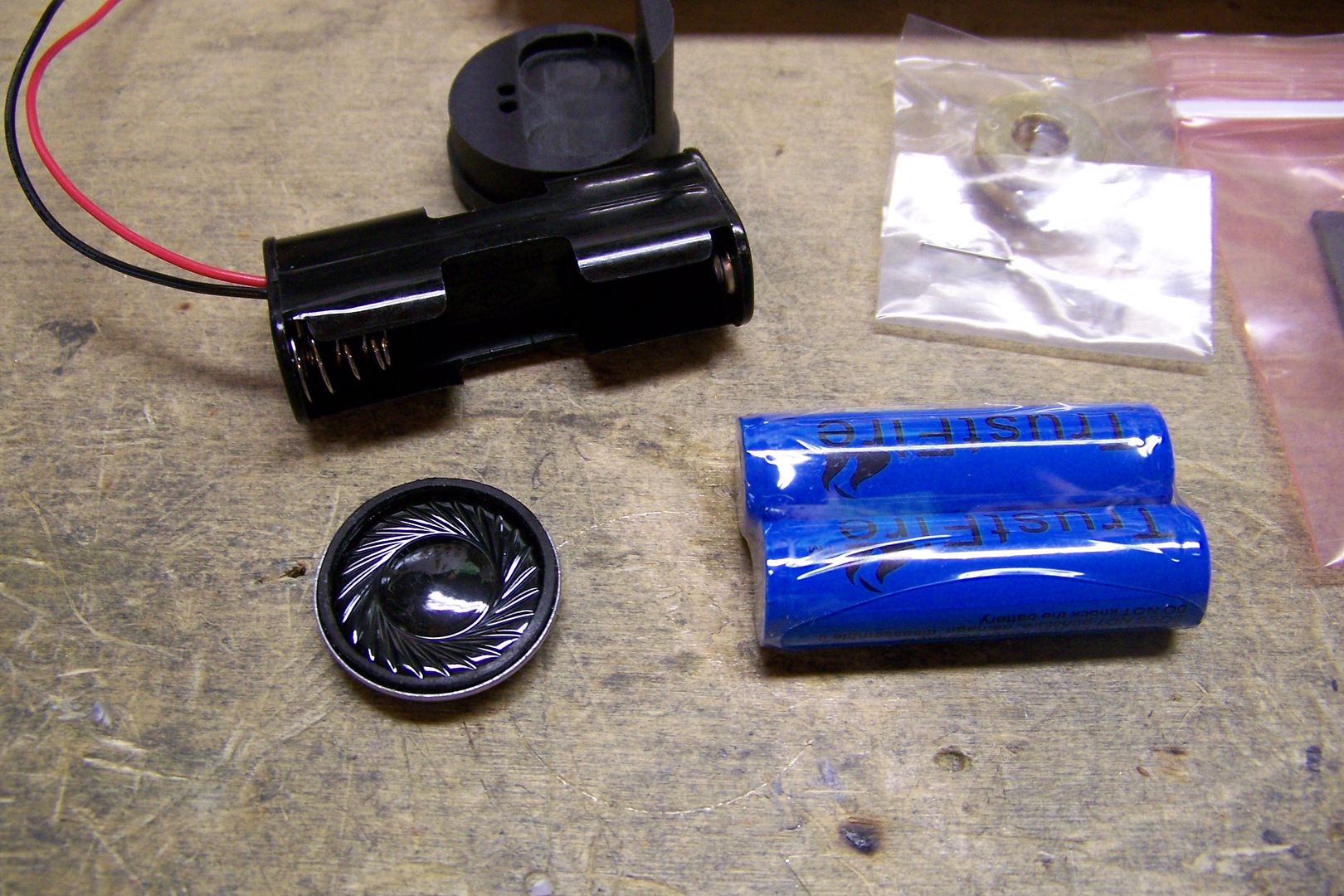
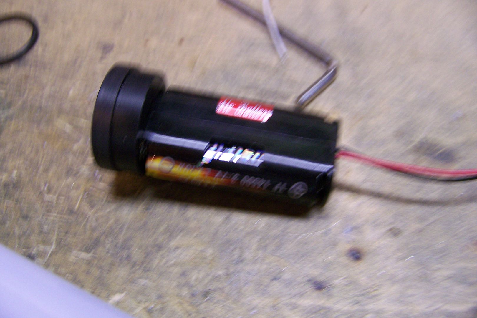
    The batteries....Li-Ion Trustfires.....premium speaker....two-AA battery holder and style 3 speaker mount.


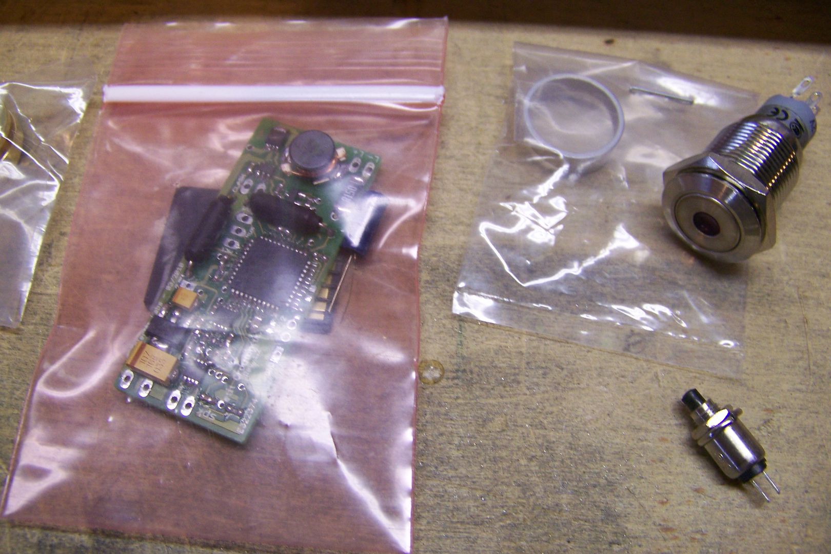
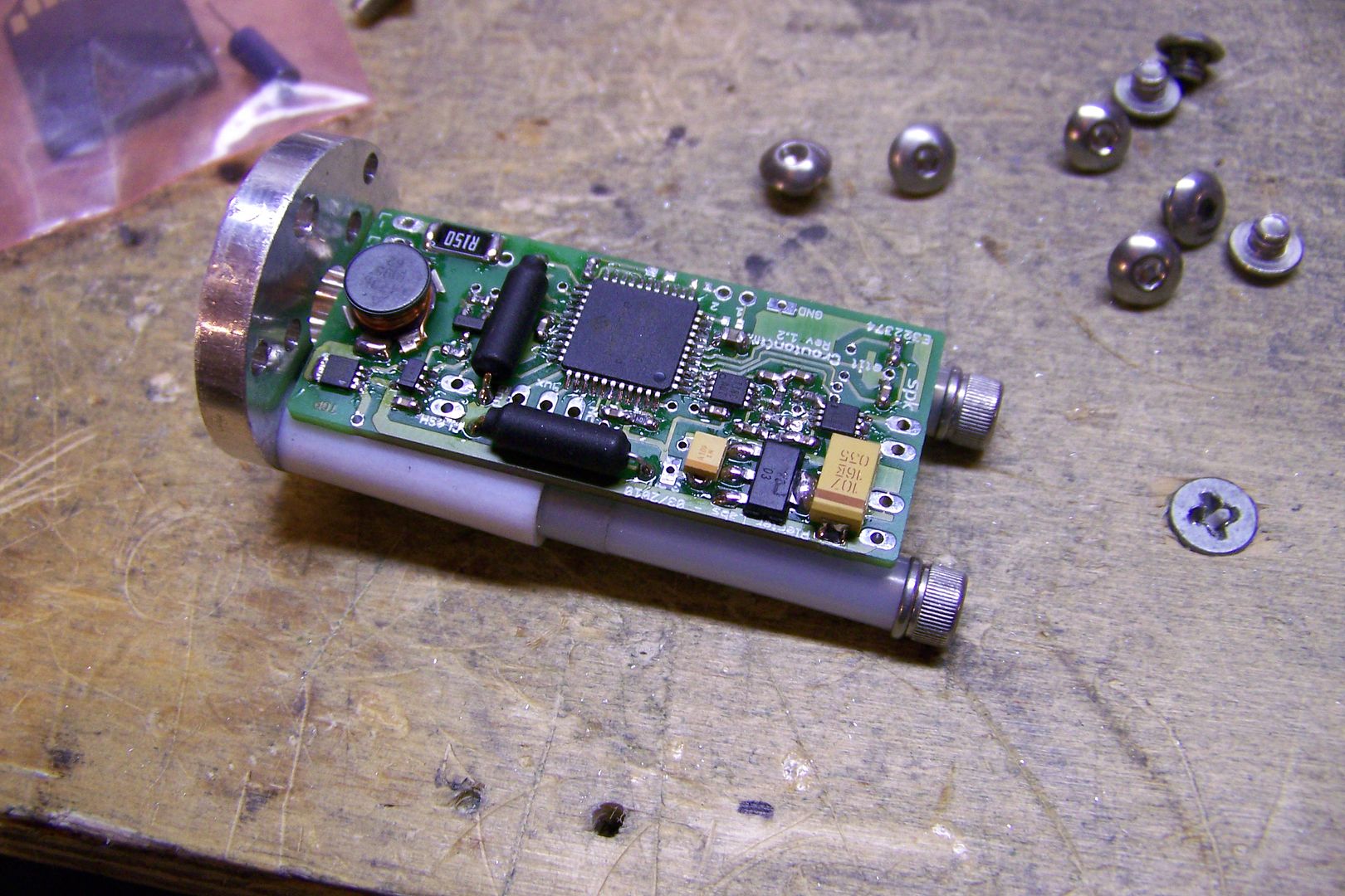
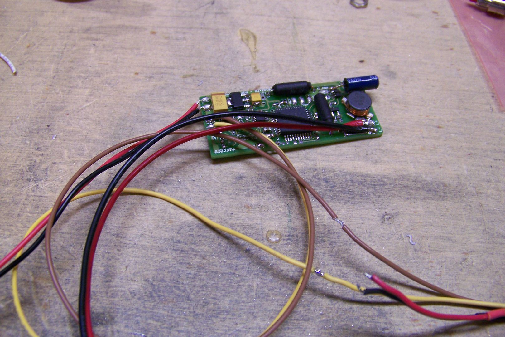
    The soundboard...a Petit Crouton. I think I'll be using the Shatterpoint font by Madcow on this one.

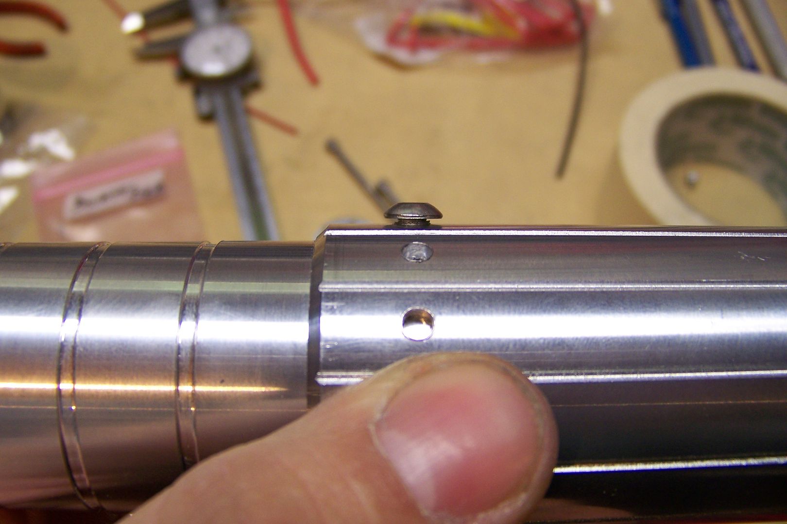
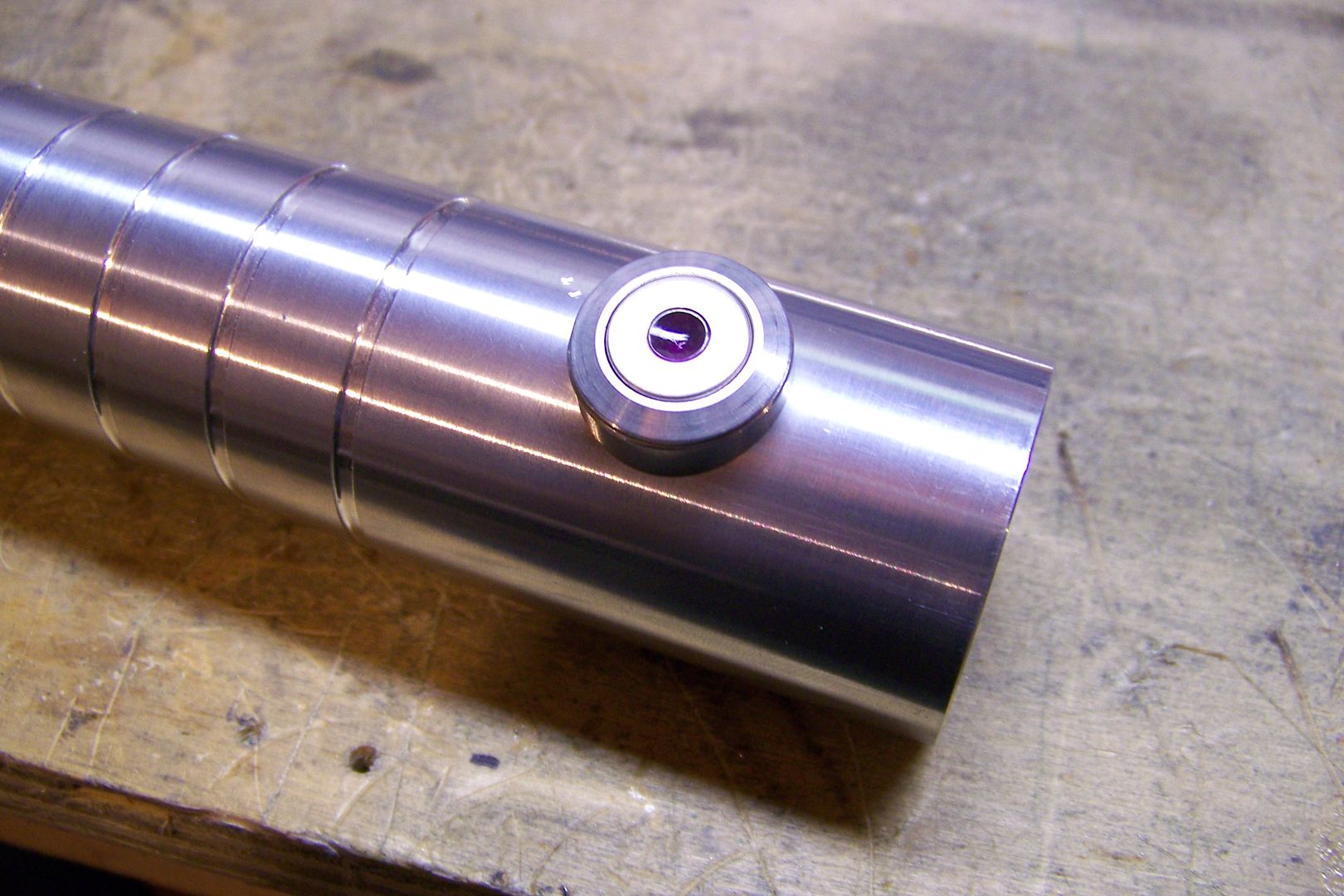
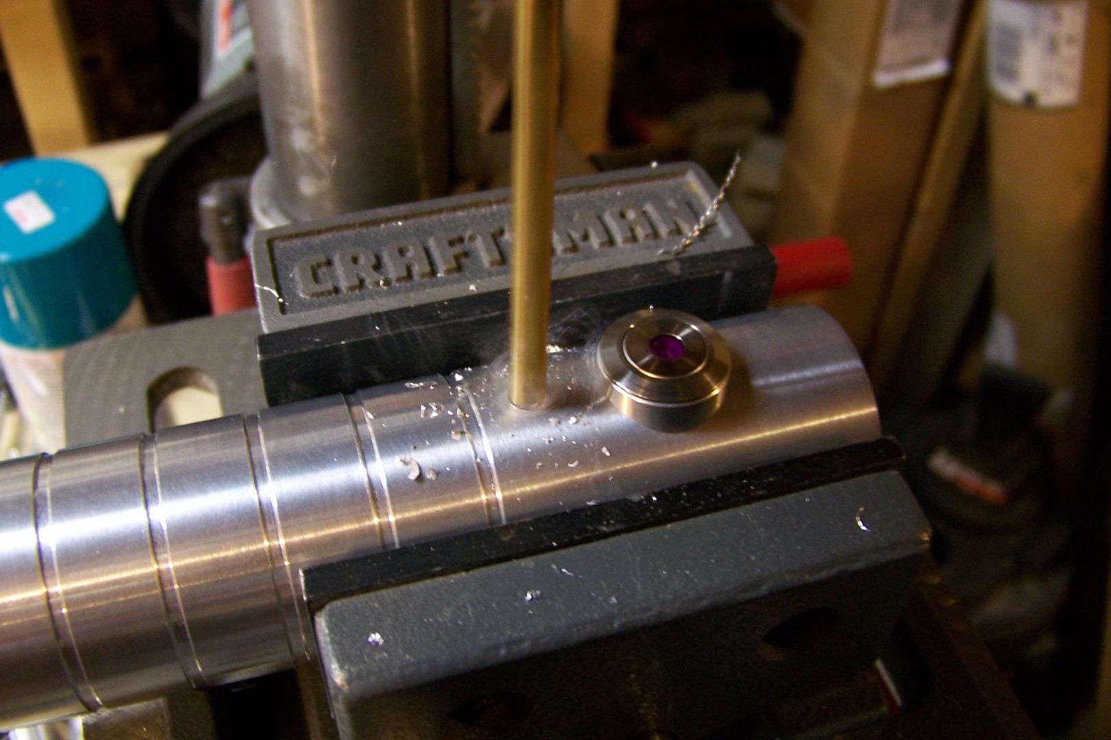
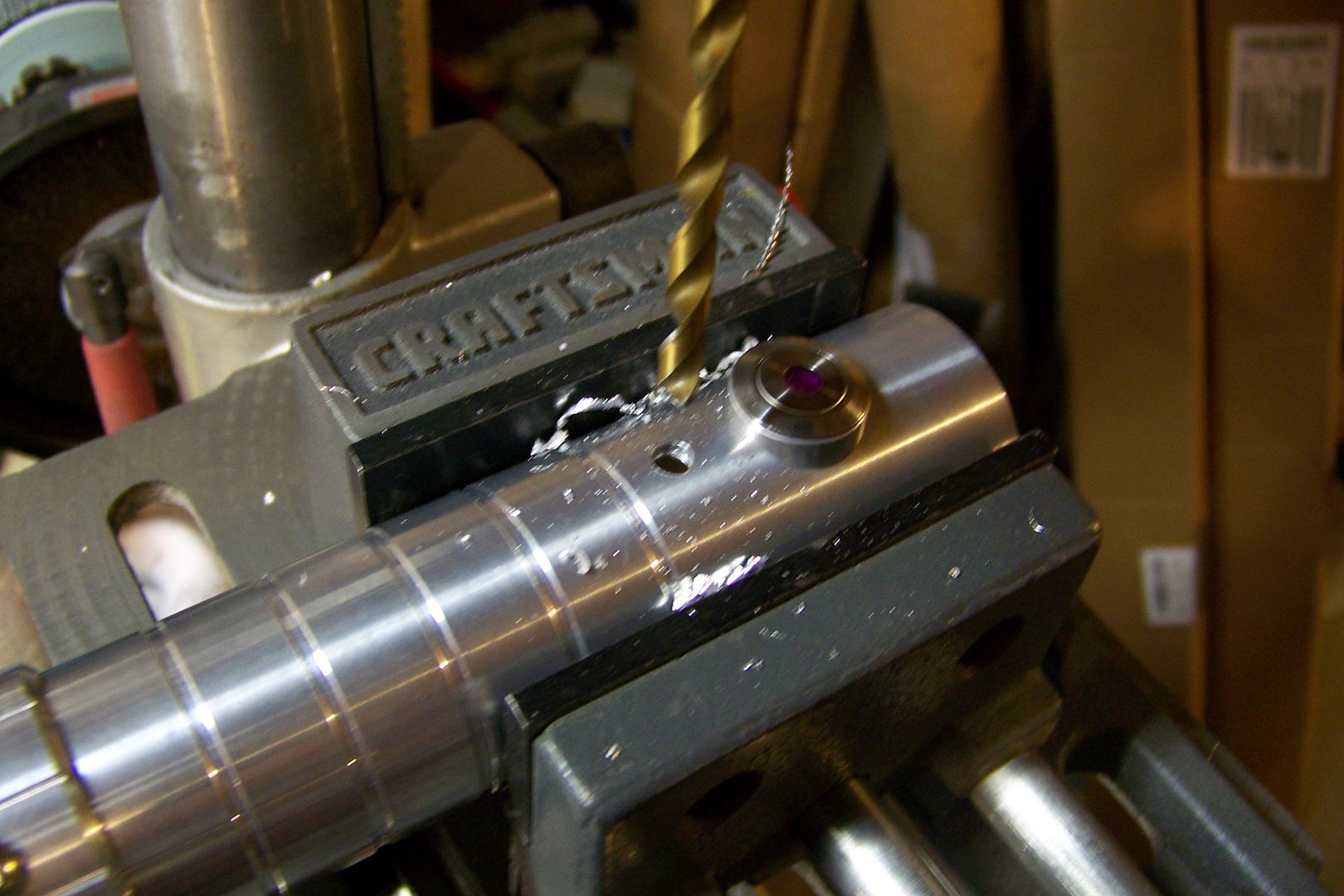
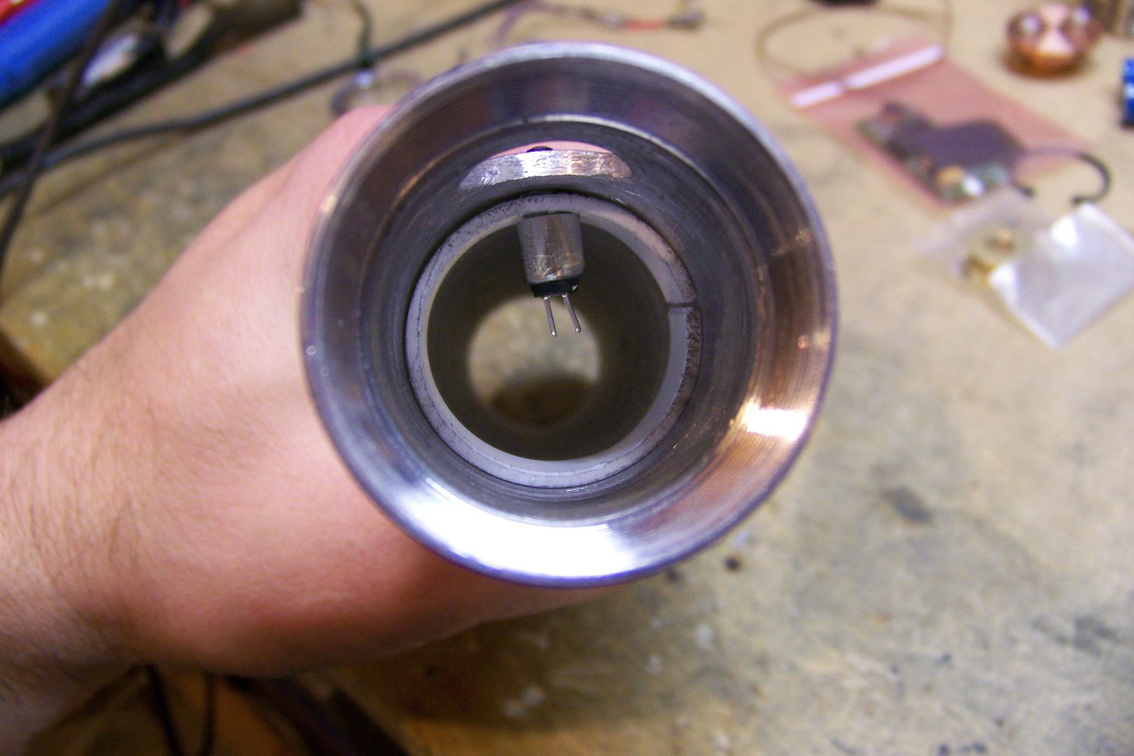
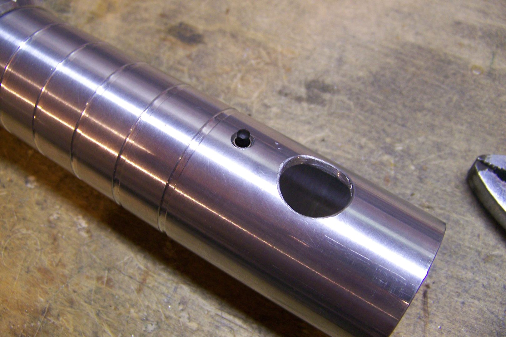
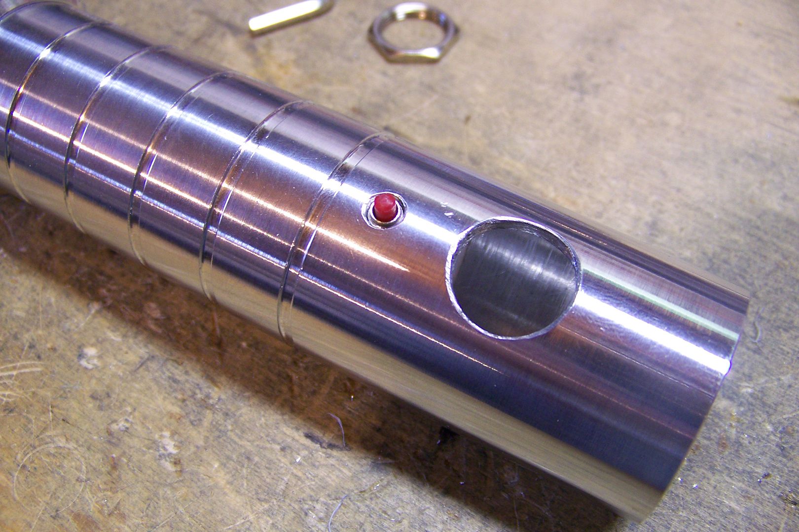
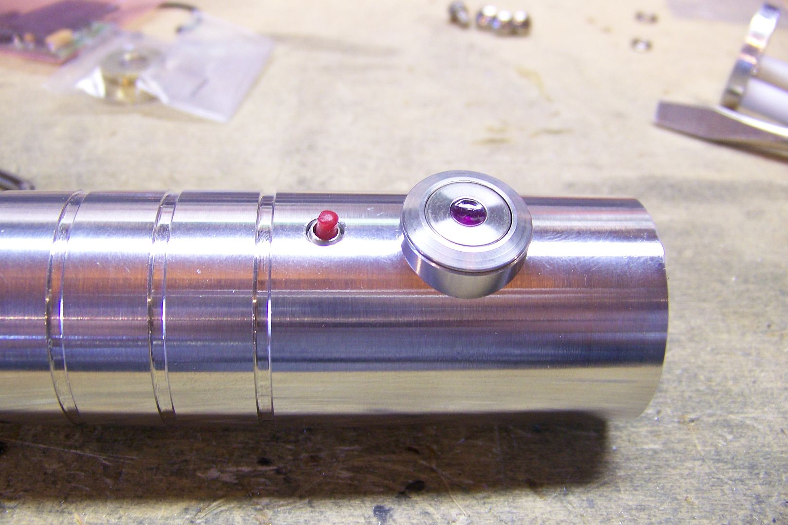
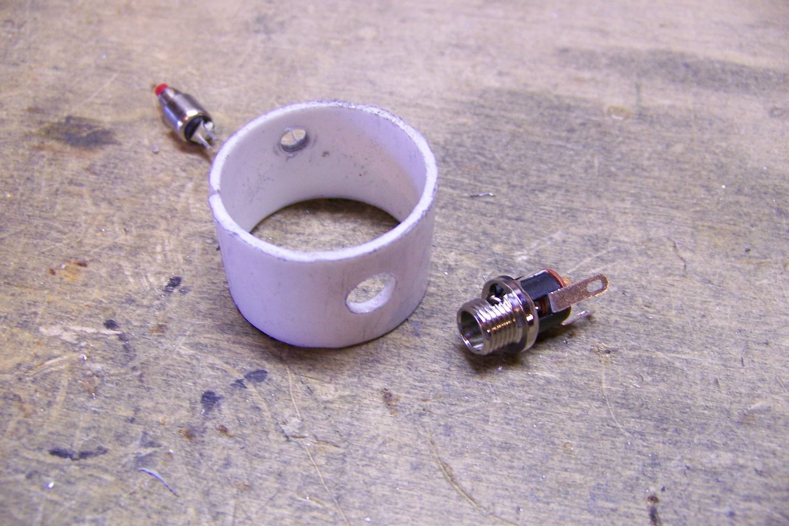
    Also seen there are the two switches...the purple dot AV is going to be the main activation switch, and the smaller one will activate the blaster deflection and the blade lock-up effects. Mara's saber actually has a control box of sorts near the emitter, but that wasn't going to work on this since the store doesn't have one that will fit, and ordering one form Parks takes forever. Even then, I'd have to have it shortened somehow, since the ones he sells are 2 1/4" long, and this saber only needs one about half that length. I think it'll look better with the light-up Anti-vandal style switch anyway.


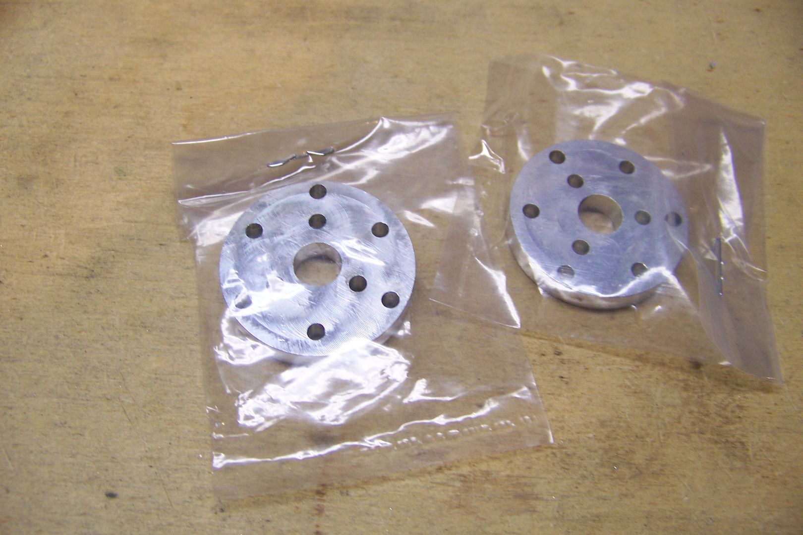
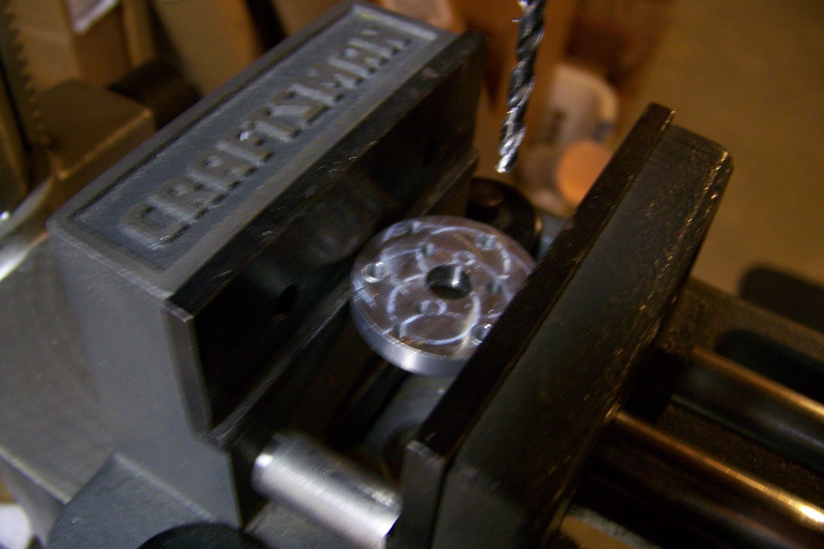
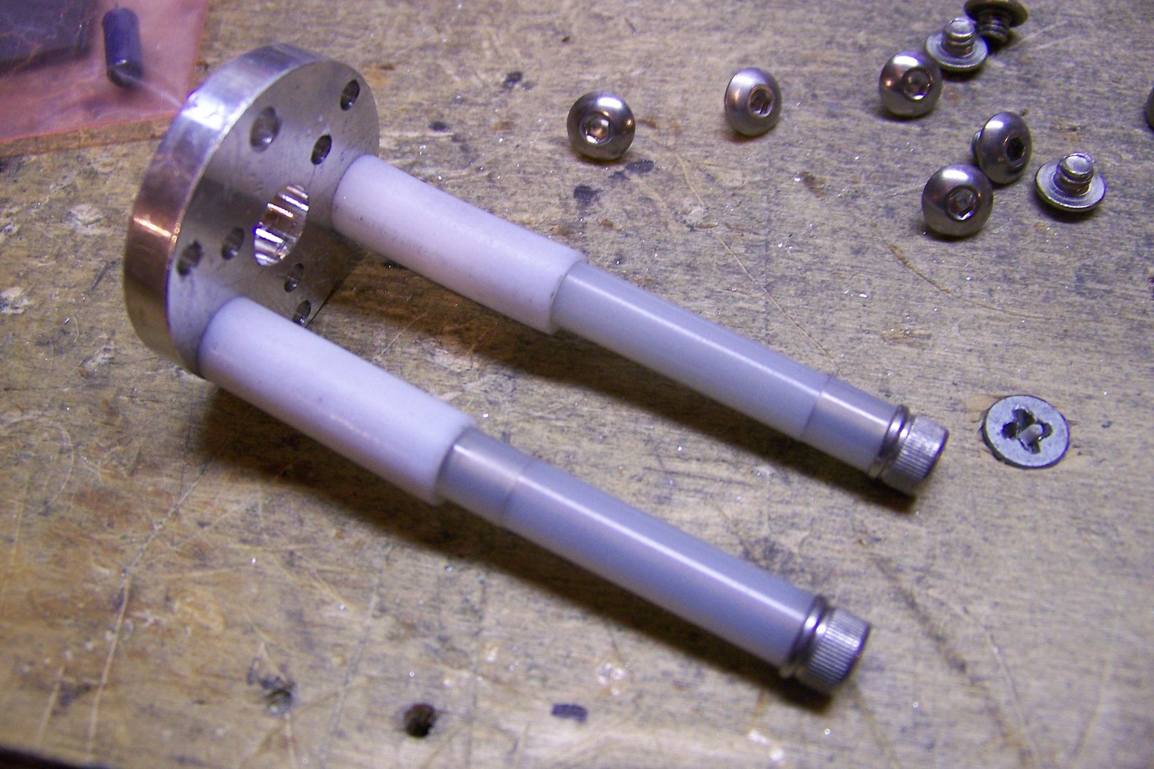
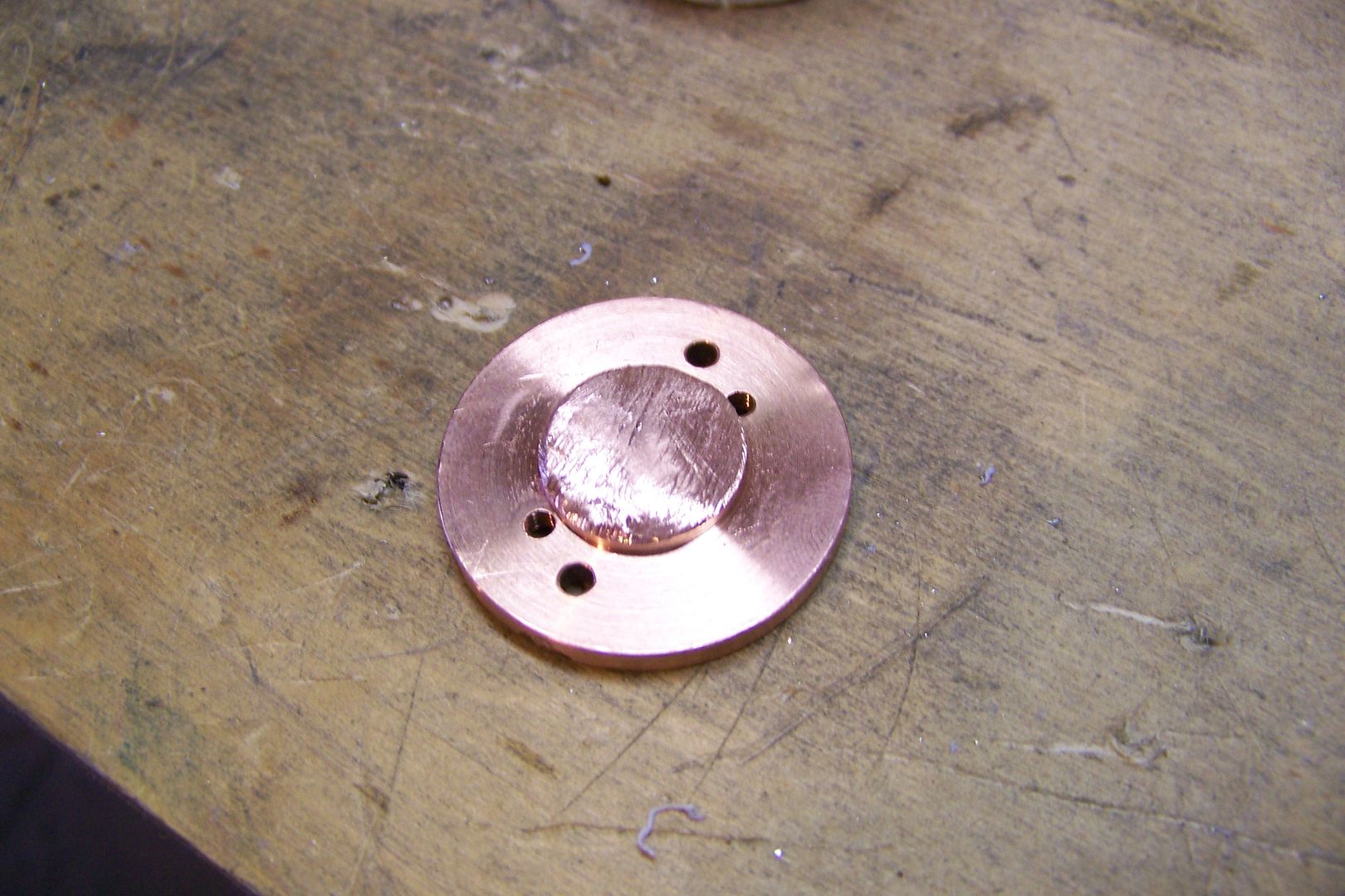
    These are the new chassis discs style 2 with holes and will be used to hold the soundboard in place. this is the first time I've used the new chassis discs, so this should be fun!


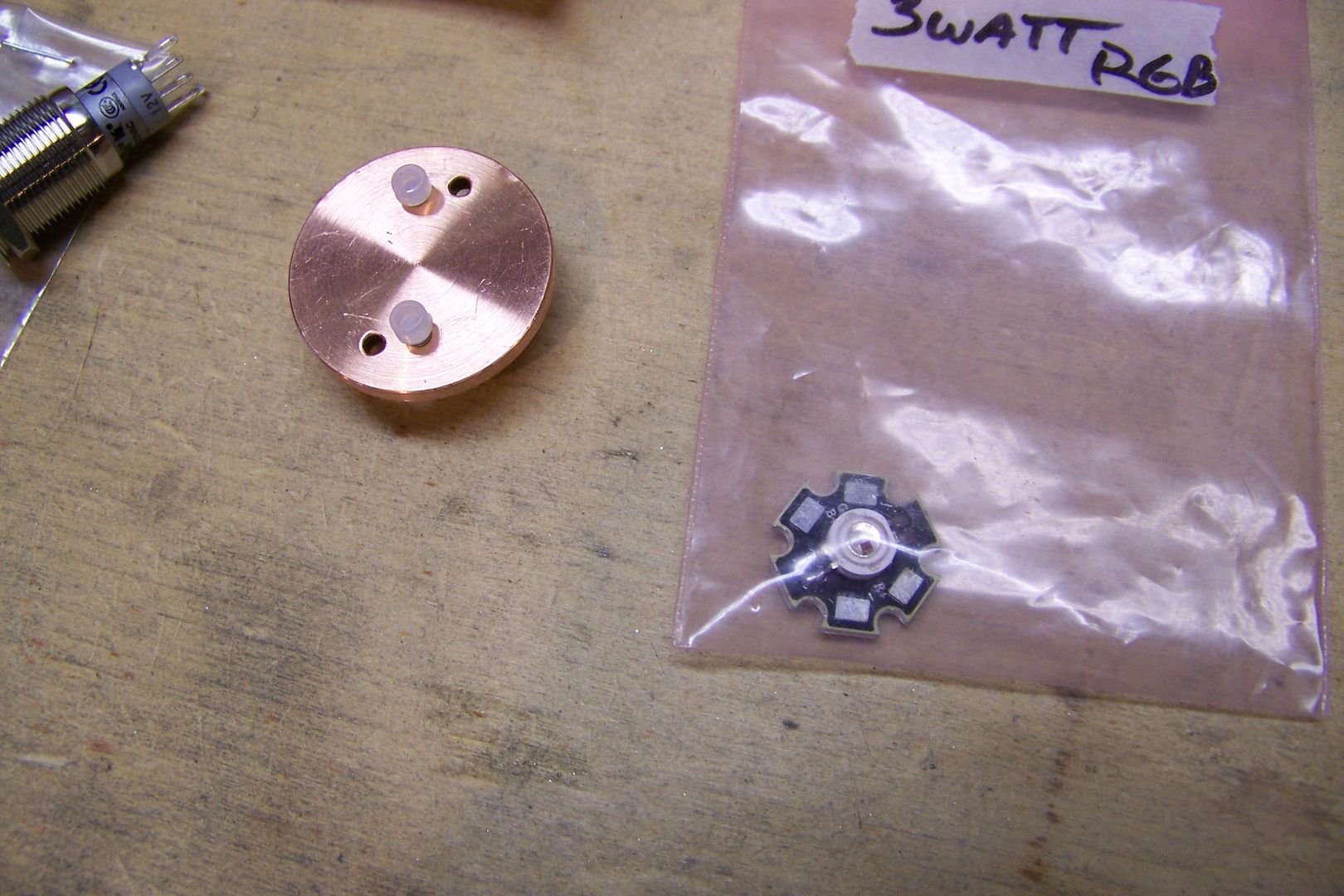
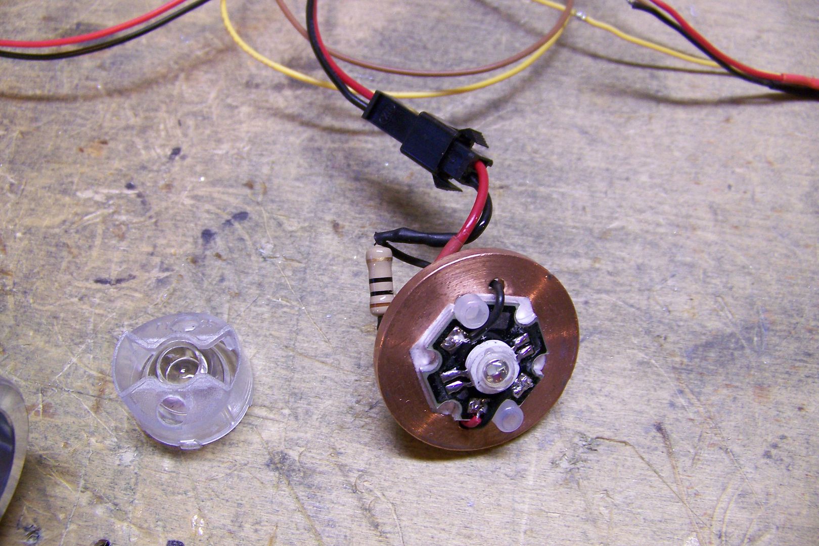
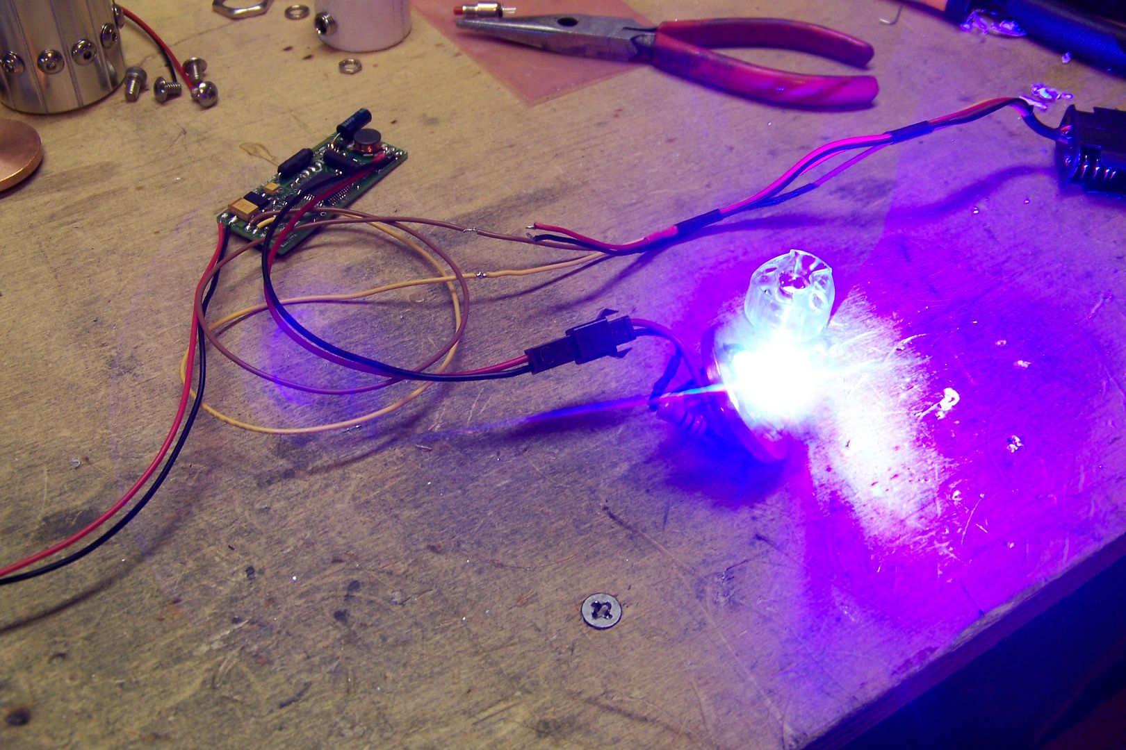
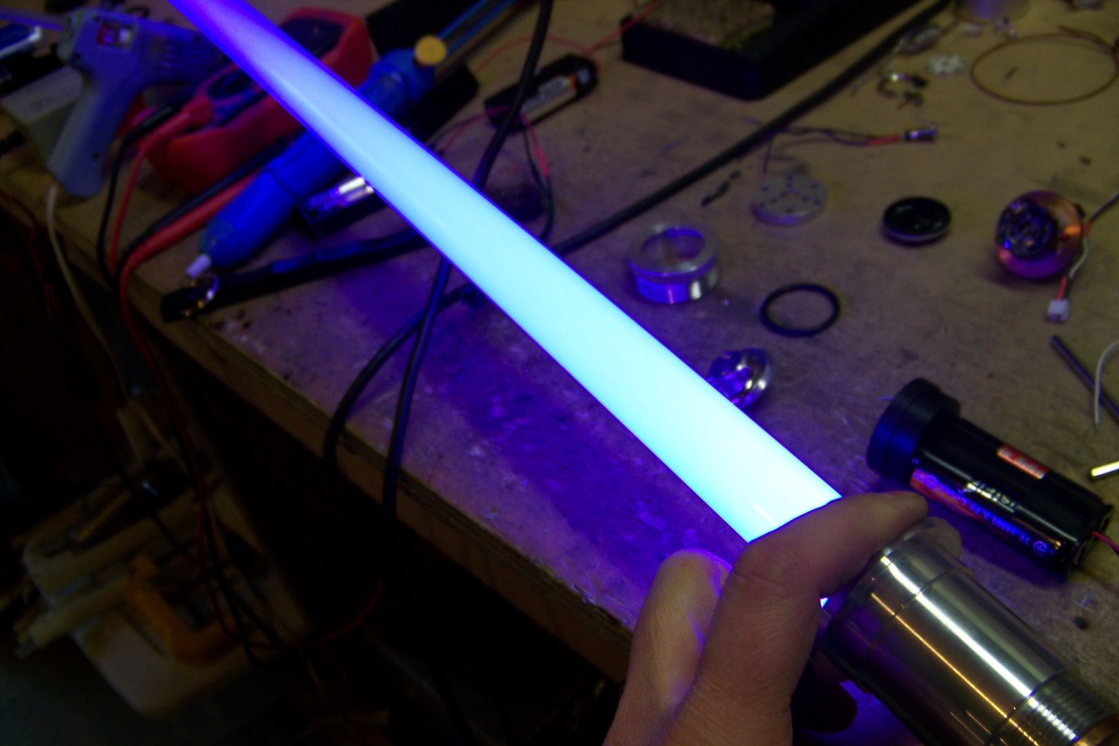
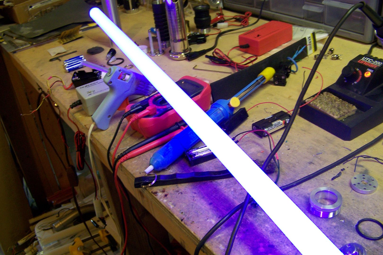
    This is the main blade led....it's a 3W RGB, and has all three main colors, red, green and blue under the center dome. I'll be using the red and blue to make a violet blade for this one similar to what I did for Chrome Saber 31.

    Got a question? Start Here. Have you tried the Thread Index yet? Most questions can be answered there.

  2. #2

    Default

    I love the Mara Jade style I'm really excited to see how this turns out!
    [Naming in progress -- saber almost finished]

  3. #3

    Default


    I figured the hardest part on this one was going to be drilling and tapping all of those holes for the screws on the rear grips, so I started on those today to get them done and out of the way.

    I set up my drill press to drill the first set on one end of the grip sleeve:

    The vise grips act as a stop for the part to ensure that they are all the same distance from the end of the sleeve and in a straight line to each other....I had to eye-ball the location on the grip to try to get them centered in each one. this would have been easy to do if I had an indexing tool to mount the part to. I made do with what I had, and drilled all the holes:

    I deburred the inside of the part using the sanding drum on the rotary tool:


    Then I test fit over the main hilt:


    Next, I took a measurement for the next set of holes...these ones need to be further in from the end of the sleeve to not have the holes interfere with the threads for the pommel:


    I reset the vise grips and drilled the next 12 holes, deburred it and slipped it onto the hilt again:


    I was hoping that I might not have to drill into the actual hilt, but I'm afraid that isn't going to happen:

    The 1/8" 8-32 button head screws I have are just a tick too long, and I'd rather drill into the hilt and tap both parts than shorten 24 screws. (in hindsight, though, that may have been quicker. )

    Using the holes in the sleeve as guides, I drilled into and through the sidewall of the hilt for each hole:


    I tapped one hole to see how well it would go:

    It went well, and I'll wait to deburr this mess until after I've tapped all of the holes:


    I tapped the rest of them:


    Since I'm planning on using the chassis discs to mount the soundboard, but really have no way to secure the discs in this saber, I decided to use three of the screws in the front part of the grip sleeve as set screws to hold the disc in place:

    I'll place three 1/4" screws evenly around the sleeve.

    These three screws should hold the disc in place just fine:


    The rear disc should fit right about here:

    There's plenty of room behind it for the 2-AA battery pack, and more than enough in front of the other one for the two switches, so this should work out nicely.

    The finished rear grip sleeve:


    So, that's all I managed to get done today....all that drilling and tapping took about 2 hours to complete, but that was the hard part and the rest should be fairly simple. The next thing I'll be working on is drilling for the main and aux switches.
    Last edited by Jay-gon Jinn; 01-11-2011 at 06:34 PM.

    Got a question? Start Here. Have you tried the Thread Index yet? Most questions can be answered there.

  4. #4

    Default


    I set it up today to drill for the main switch:

    I started with a 3/8" bit and drilled, then switched to a 5/8" for the illuminated anti-vandal switch size:


    I de-burred the hole using a sanding drum on the rotary tool:


    Then test fit the switch:

    The second aux switch will go right behind it. I drilled the hole for the main switch where I think it should have gone, and after looking at it again, it's a little too far forward for the heatsink for the led to fit....I'll have to remove the "nub" from the back of the heatsink for it to fit. I've done it before on a few other sabers that needed extra clearance, and it works fine.

    The next thing i worked on was the chassis discs....I decided this saber really only needs one to hold the soundboard, so I drilled out three of the holes that were already there to accept an 8-32 screw:


    Then tapped the holes, added some spacers and made up a soundboard mount:


    The soundboard fits on top of the screws like so:


    I put the soundboard back into it's anti-static bag, then test fit the soundboard mount in the saber:


    It slid all the way down to where the first set of screws are in the rear grip:


    I should be able to use one of the grip screws to act as a set screw to hold the chassis disc in place, thereby locking the board in position inside the hilt:

    I had to spend a bit of time on the hilt using a cylinder hone to clean out the inside diameter....the chassis discs are a very snug fit, and after drilling into the hilt, it made the discs impossible to get through the section that had been drilled in. It fits fine now, and should work like a charm.

    I'll work on the placement for the secondary switch tomorrow.
    Last edited by Jay-gon Jinn; 01-12-2011 at 06:28 PM.

    Got a question? Start Here. Have you tried the Thread Index yet? Most questions can be answered there.

  5. #5

    Default

    So one disc balances well? Your board won't bounce up and down on one end?

    I would think deburring a hole before tapping would be more logical since you have to bring your tap forward and back and you might pull shavings into the thread and damage it...maybe I'm just being too cautious/paranoid.

  6. #6
    Jedi Knight
    Jedi Knight
    Azmaria Dei's Avatar
    Join Date
    Dec 2010
    Location
    Zama City, Japan, Sol 3, Gould Belt, Milky Way Galaxy, Virgo Supercluster
    Posts
    1,022

    Default

    Quote Originally Posted by Crystal Chambers View Post
    So one disc balances well? Your board won't bounce up and down on one end?

    I would think deburring a hole before tapping would be more logical since you have to bring your tap forward and back and you might pull shavings into the thread and damage it...maybe I'm just being too cautious/paranoid.
    i've been deburring before and after tapping...

    looking great JGJ! can't wait to see it finished. ^_^ i do have to wonder about the single disk as well, though...
    CLICK HERE FOR ALL YOUR ECONO SOUND BOARD WIRING DIAGRAM NEEDS!

    Duel - to fight someone 1 on 1. Dual - 2 of something in line with each other.
    Quote Originally Posted by Multiple People
    To Azmaria listen you should...

  7. #7

    Default

    I also ordered some of the chassis disks so for me it's very interesting to see how you are going to mount the soundboard. Until now I mounted my soundboards with double-sided adhesive tape but that is not possible hear. How are you going to do it?

  8. #8

    Default

    I usually use double sided tape, too, but I'll cover that when I get to it.

    I worked a bit more on this saber this weekend, and here's what I got finished....

    I made up the mounting clip for the aux button:

    This is made form a small section of a 1 1/4" pvc sink drain extension.

    I drilled a hole and used the switch itself to make the threads for the hole, since I don't have any metric taps (The threads on these switches is M5 x .5):


    I then drilled a 13/64" hole in the hilt just behind the main switch in a spot that won't interfere with the nut for the main switch:


    I used a pair of cutting pliers to split the pvc ring into a c-clip, and checked the fit:


    I cut too much of the c-clip out when I cut the ring, so that allowed the switch to have too much compression when it was pressed, so I cut a new, larger c-clip and replaced the other one.

    Then I figured it might look better with a red button, and changed it:


    The new clip is also long enough to house a recharge port, which isn't required for this saber, since it will have removable batteries, but may come in handy for shutting down the board without having to remove the pommel, and pull a battery:


    I installed the main switch to use as a reference for drilling the hole for the recharge port, to ensure it was directly opposite and in alignment with the switch:


    I loaded the hilt in the drill press' vise, and drilled a pilot hole:


    Then drilled the hole for the recharge port using the pilot hole as a guide:


    With the c-clip installed in the saber, i also drilled the hole through that. the bit I used happened to also be the correct one for the tap for the threads on the recharge port:

    I tapped the c-clip for the recharge port's thread size (5/16-32) and threaded it into place. I'll have to come back to the hilt and re-drill the hole to allow the recharge port to fit through using a 5/16" bit.

    The last bit of cutting and drilling I need to do for now on this one is removing the nub on the heatsink so it will clear the main switch body:

    I used a cut-off wheel on my rotary tool to start cutting through it, but then thought better of it and took it up to the garage and use my hack saw....that was a little faster. I cut it off, then brought it back to the basement where my bench is, and used the rotary tool to sand it smooth and de-burr it.

    There is now plenty of room for the switch and the heatsink together:


    I loaded the hilt back into the drill press and drilled the 5/16" hole:


    With all of that done, I started prepping the PC for installation into the hilt....I added the clash sensor, a few wire leads, and loaded the sound font onto the microSD card, then did a temp wiring job on it to test it:


    I borrowed the completed RGB Violet led I have made up for CS-35:


    Installed two Trustfire 14500 Li-Ion batteries:

    I immediately heard the boot sound for this font, "This party's over"....cool....

    I used a pair of tweezers to activate the board:


    I slipped the blade holder over the led, added a blade and took another couple of pictures:


    It looks like when I wire up the led for this saber, that I'll have to use a lower value resistor than what I did for the led for Cs-35....that saber will be powered by an Ultrasound 2.5, and a 3.7v Li-Ion battery so that required a different resistor to achieve the shade of violet I was looking for on that saber.

    Since I know it works, I can start assembling this one, and hopefully get it closer to being finished tomorrow. I still need to get the Graflex red button thumbscrew for the blade retention screw, and that could take some time to get hold of, since Tim is out of them.

    Got a question? Start Here. Have you tried the Thread Index yet? Most questions can be answered there.

  9. #9

    Default

    Its looking cool, the placement of the switch is nice.

    Will you still wire in the recharge port for charging (i.e the positive lead), or just wire it to kill power with the 2 negative leads?

    Click here to learn all about me!
    The Shoutbox: The only place you can double post!
    Anybody who spells it Lightsabre is dyslexic
    "Yeah, if I had Skotts face I'd hit it too" ~ Fenderbender
    "You didn't buy a toy saber just to break it. You bought an economy sound card with a really complicated wrapping scheme." ~ Silver Serpent

  10. #10

    Default

    Yes, I still wired it for charging if it ever becomes necessary. I also plan to use a QD on the battery pack so in the future, if it ever needs a rechargeable pack installed I'll be able to do that without totally dismantling the saber.

    Got a question? Start Here. Have you tried the Thread Index yet? Most questions can be answered there.

Bookmarks

Posting Permissions

  • You may not post new threads
  • You may not post replies
  • You may not post attachments
  • You may not edit your posts
  •