


Since there are so many differences with the Hasbro FX Board with Removable Blade, I thought a new wiring diagram is in order. It seems everything we were used to with the fixed blade FX board has been changed. Also, the pololu and lighthound boards will not work with this board. I spent 2 hours figuring that out. I used the same pololu board on a Yoda FX and it worked fine. The problem is with the removable bladed FX board switching the - instead of the + like the fixed blade ones do. The first thing I did was get rid of all the hot glue and resolder all the wires I needed myself. Hasbro has been known for sloppy soldering. Anyway, here is the diagram with a recharge port, illuminated AV switch, remote clash sensor and a single 18650 Li-Ion battery.
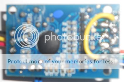
Here is a pic of the back side of the board. I jumpered the pre to the gnd and also I took a 2" piece of stripped wire, pre-tinned it and soldered it on L1 - L6. That way you don't have a bunch of wires in the way.


 Reply With Quote


Bookmarks