


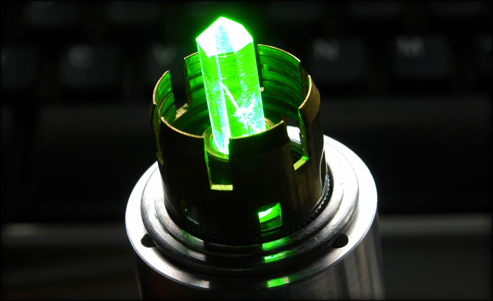
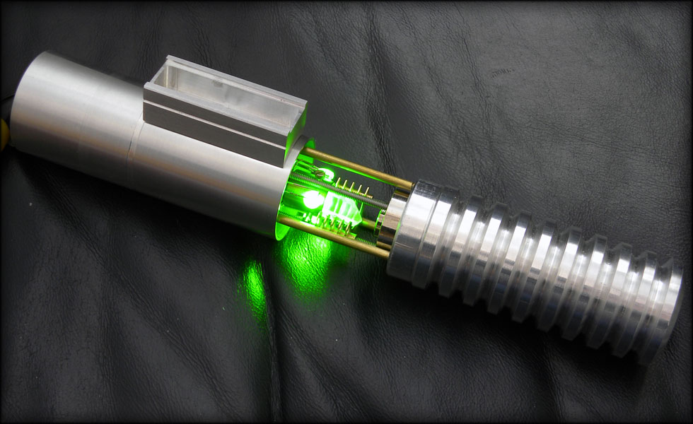
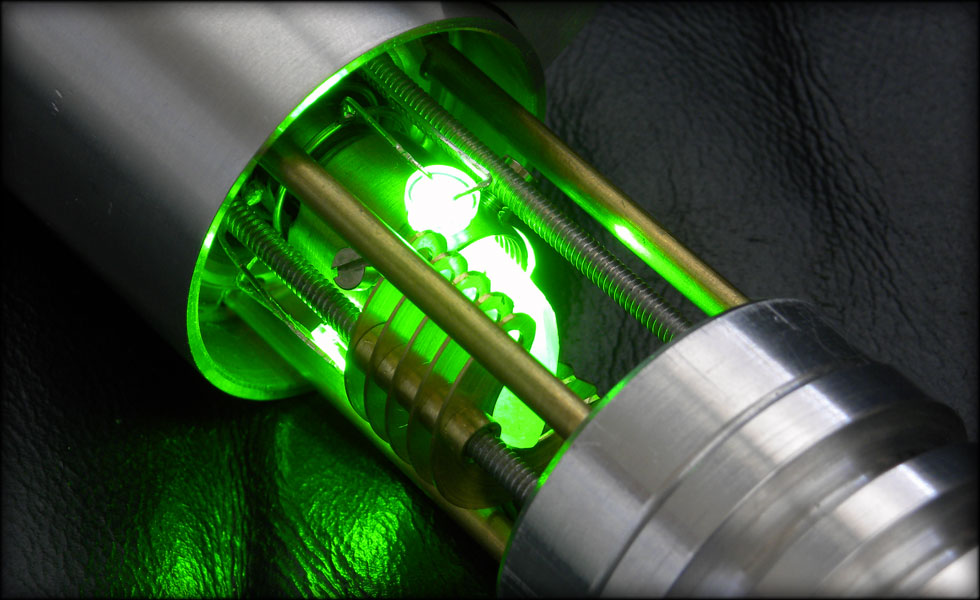
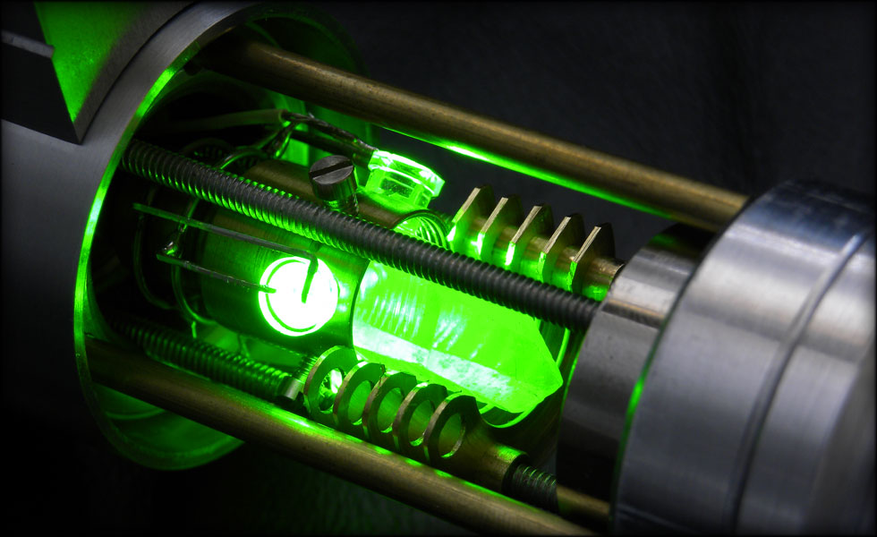
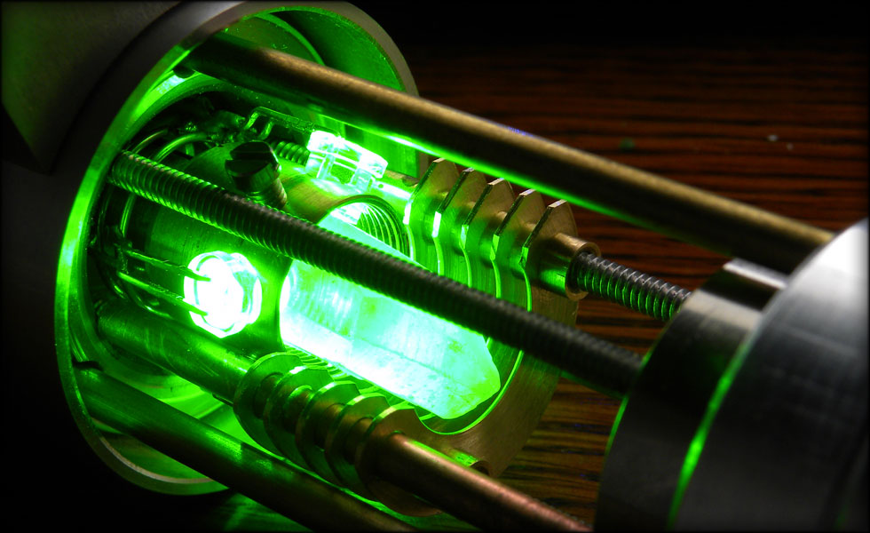
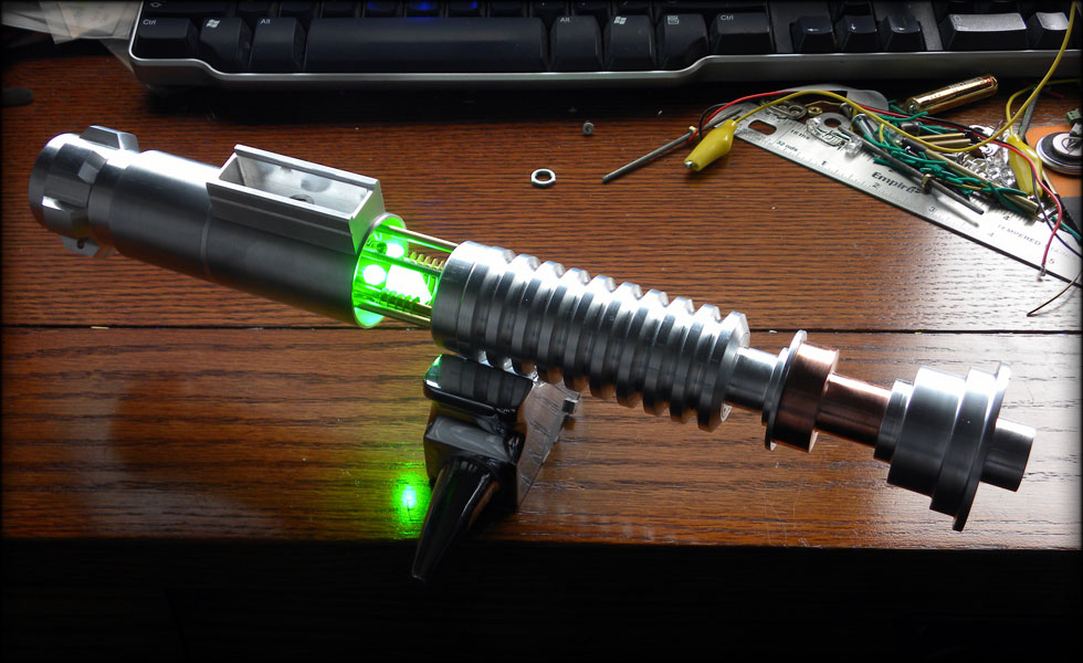
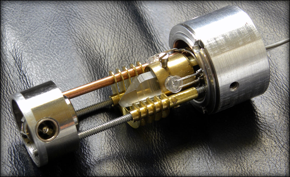
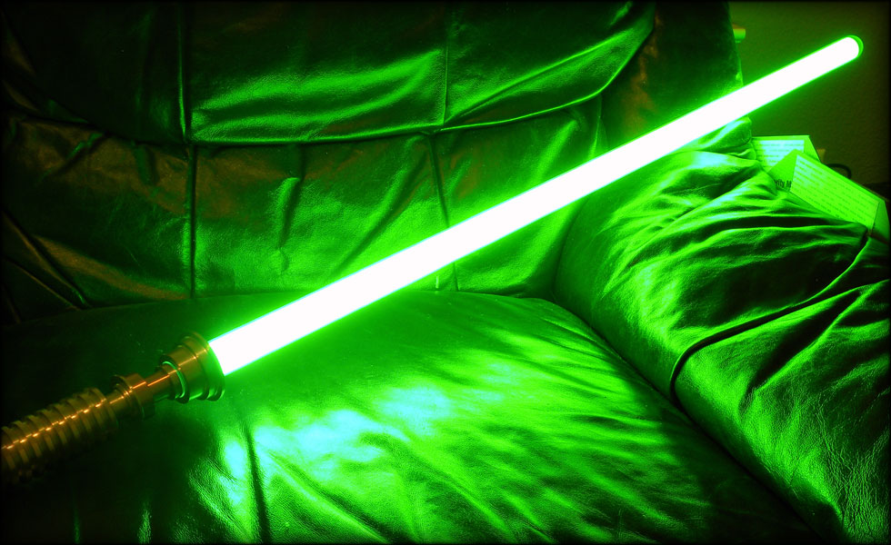
It is time now to post this saber, I'll be bombing this thread with posts till I get the bulk of the build log in here, but this is a Return Of The Jedi Luke Saber, with crystal chamber, thin neck, and detachable blade.
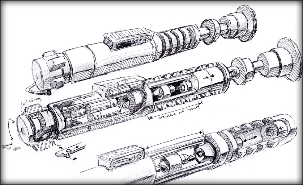
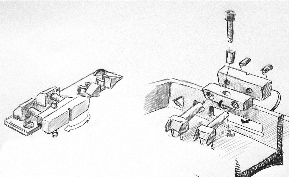
My initial sketch of the project, I *think* I can get it all in there.
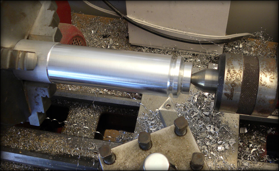
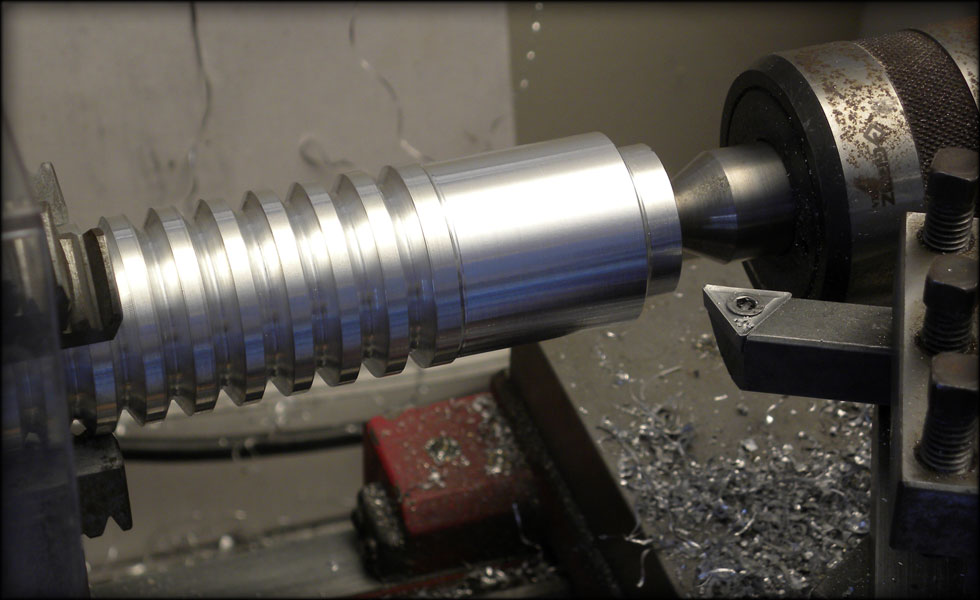
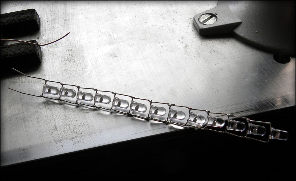
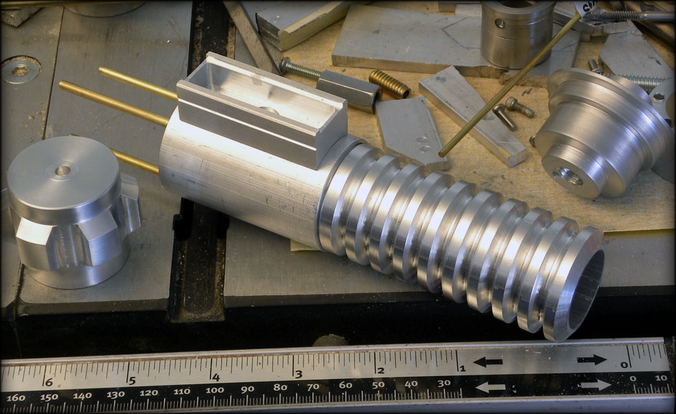
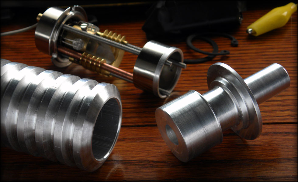
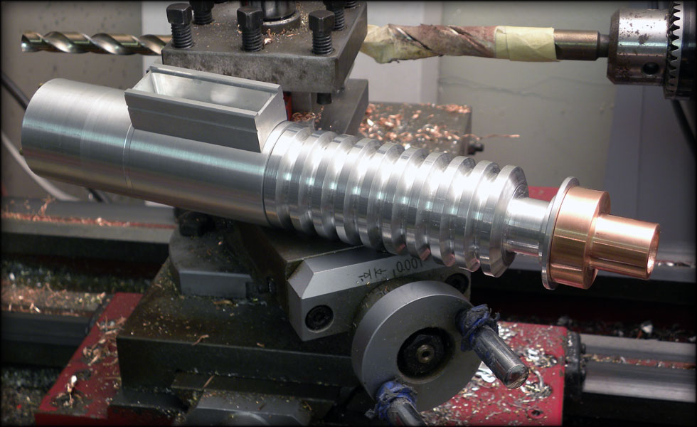
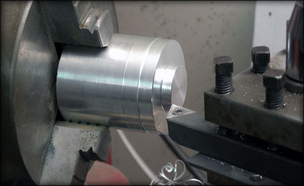
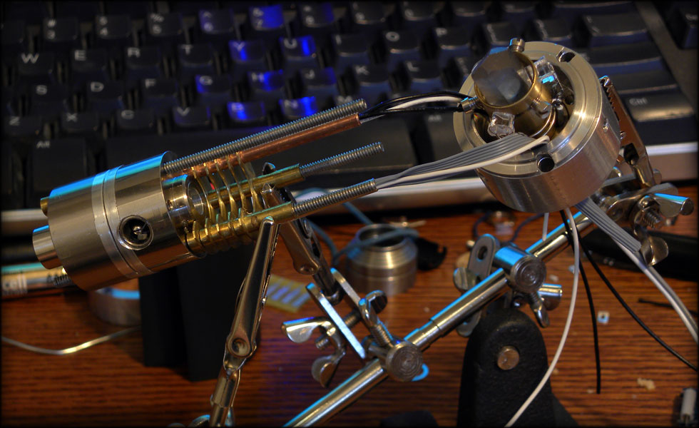
I begin with the key to the project, the collapsable grip section, first I must replicate this part, in hollow 1.5 inch diameter aluminum.
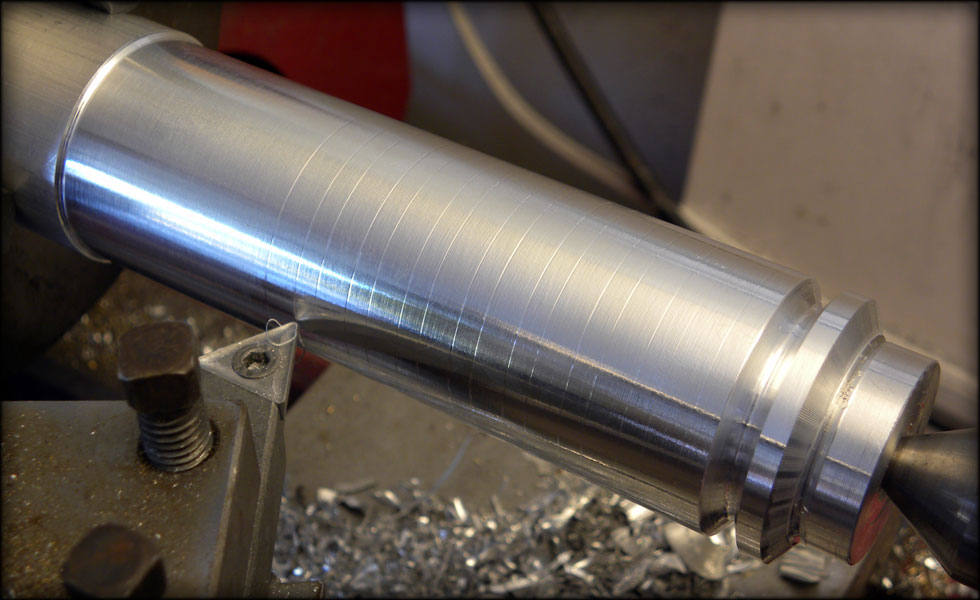
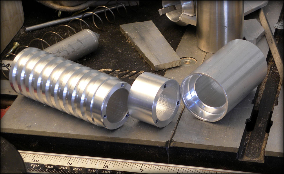
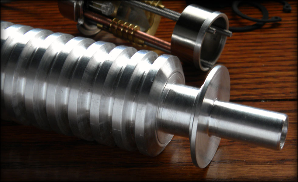
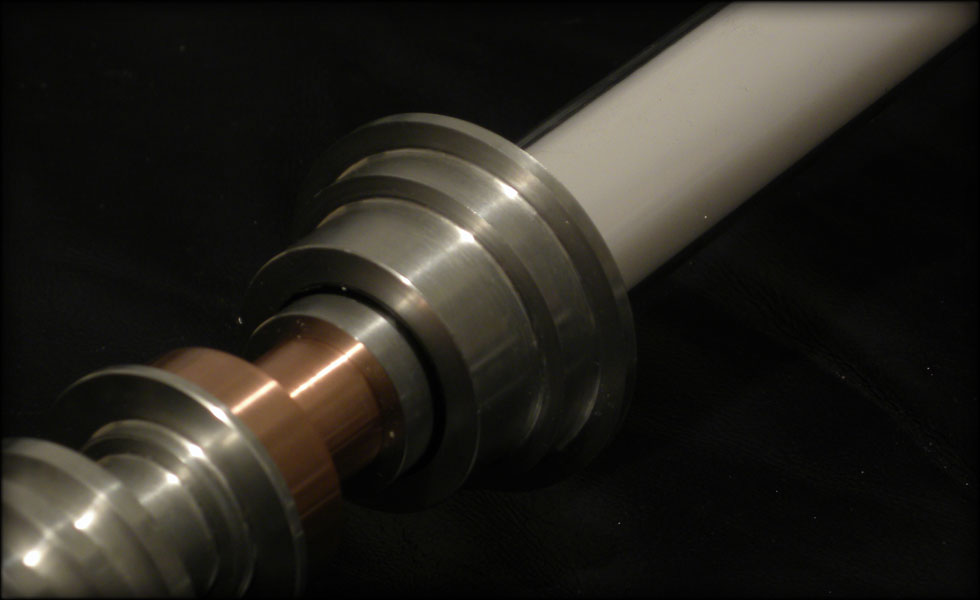
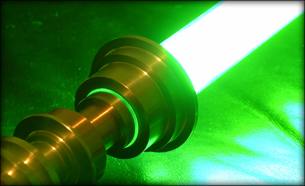
After I got my first groove cut, I measured out 0.32 inches for each successive groove, marked it lightly with my lathe, on each side of the groove, thereby giving me a place to "color in the lines" so to speak, and to take the groove down to a set depth on each ring.
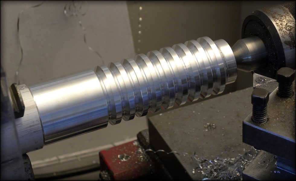
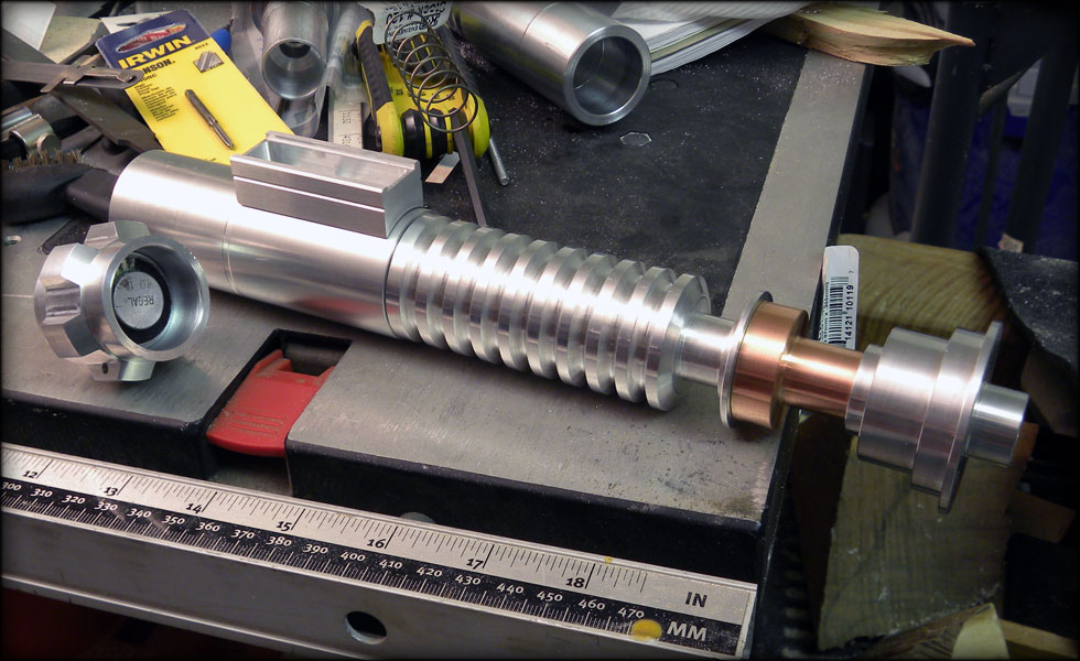
Here are the grooves cut, I have a bit of chatter in one or two, but that's easily solved with some sandpaper. The grooves will be painted in the end, so it won't matter too much. I also made sure to use a slightly more rounded tip on my cutting bit so as to let the inner diameter inside the grooves leave enough material to be strong, with the grip section being hollowed out to one inch.
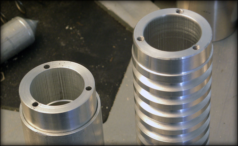
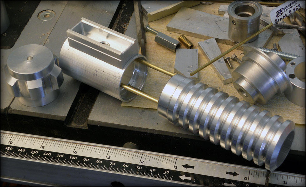
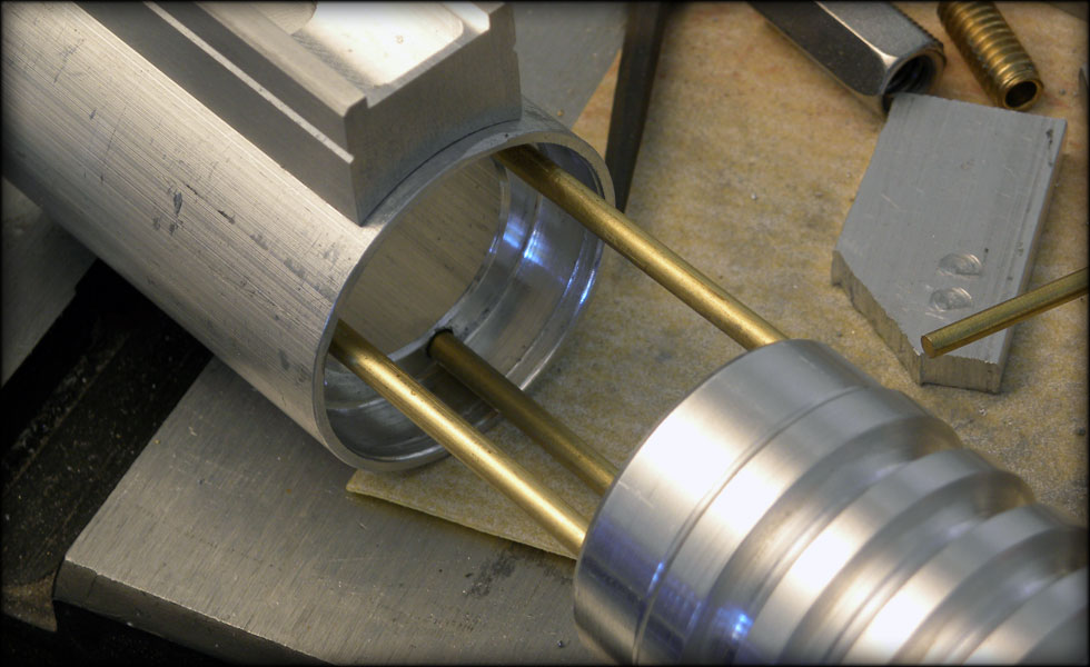
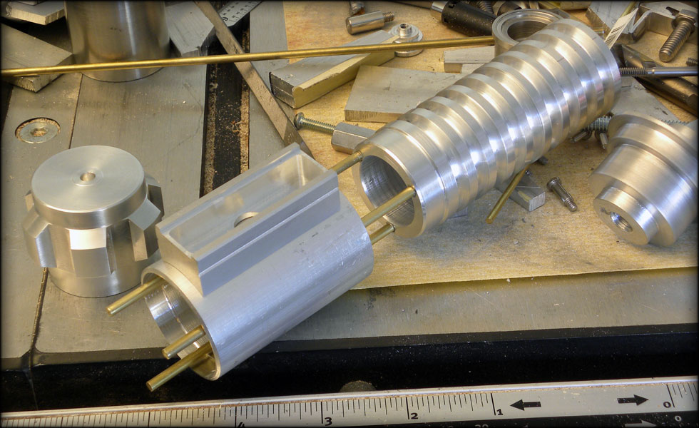
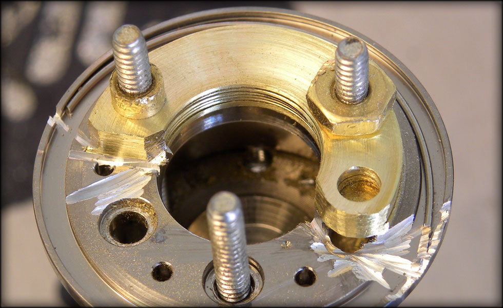
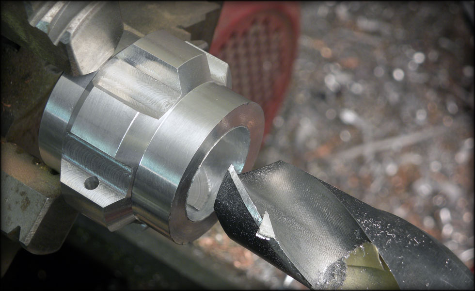
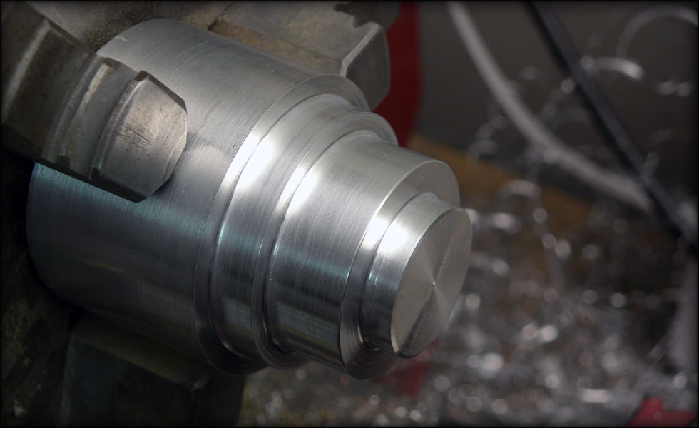
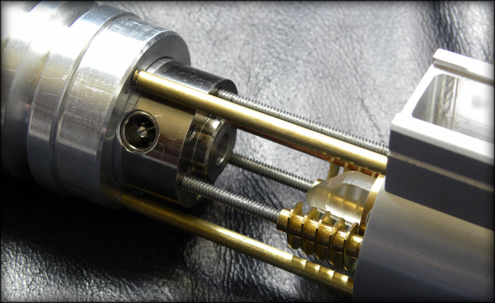
Here I turned the grip section backwards to cut the smaller diameter behind the grooves. This will fit inside the main rear grip section underneath the control box, and be cut so that I have a retaining ring to let my rods go through for the collapsing bit.


 Reply With Quote
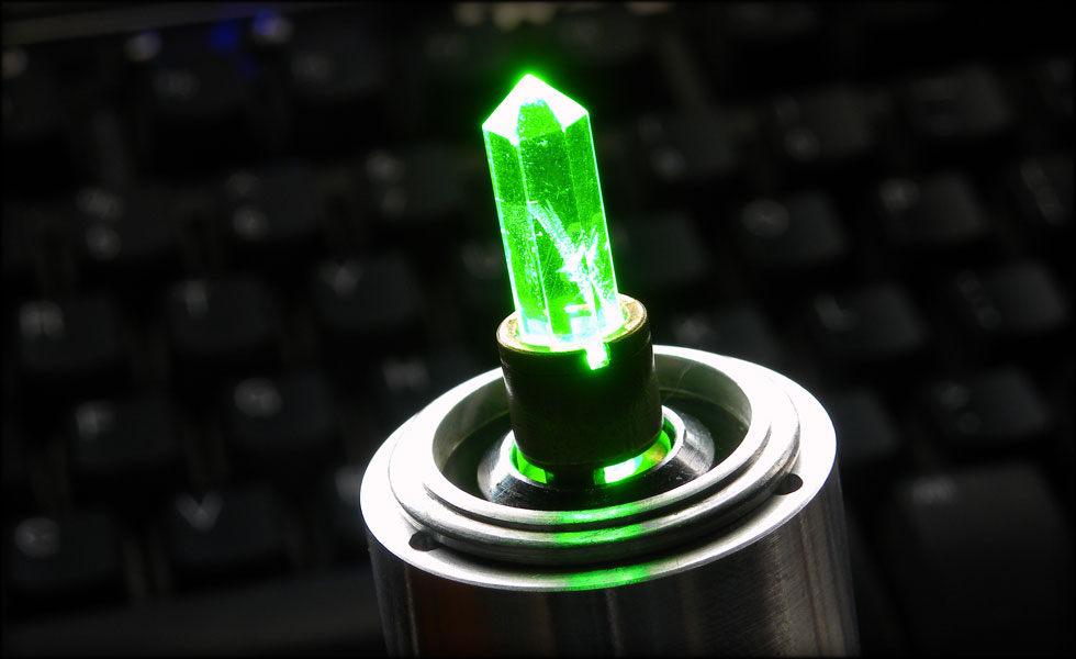

Bookmarks