
Originally Posted by
Gin Malinko

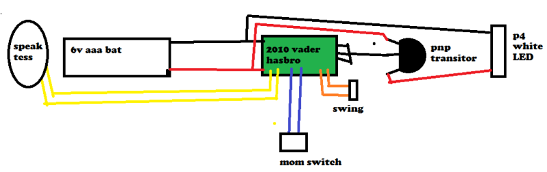
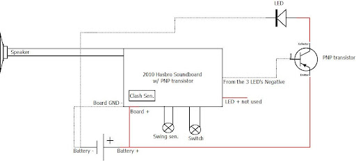
Yeah thats the diagram i used to wire this up. mine looks a bit different in the wiring diagram but its pretty much the same.
i just wanna know how i can make the p4 brighter. in one of novastars post i saw he mentioned something about maybe using a capasitor, because the p4 takes a little more to power, and with the hasbro board i would imagine that voltage coming out isnt as much as it could. i bought a multimeter but it doesnt come close to being able to read anything -_- only goes up to 250 ma
if anyone would like, i could upload direct pics on the wiring


 Reply With Quote


Bookmarks