It looks like you're shorting the LED. it looks like the bare wires are touching the copper heatsink.


It looks like you're shorting the LED. it looks like the bare wires are touching the copper heatsink.

The wires were touching, and that's been corrected now, thanks Phoenix.
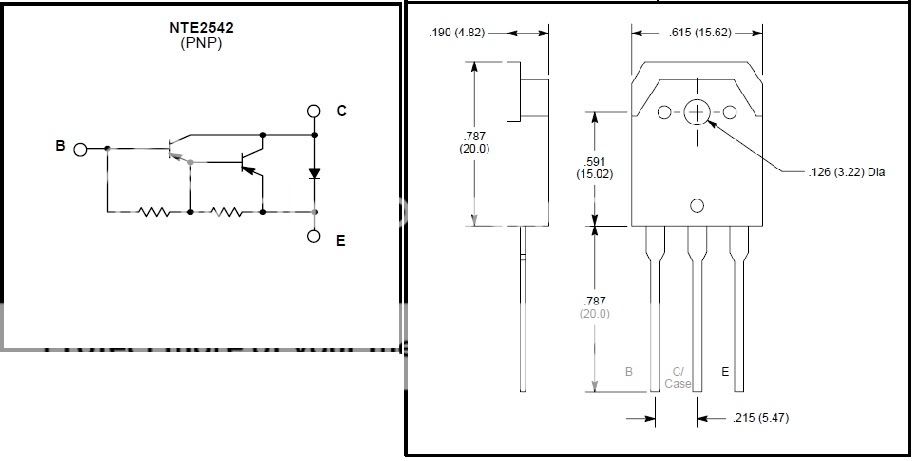
Unfortunately I'm still getting no sound or lights. My gut is telling me I've got the wrong transistor (But my confidence has been shot with this project, and could be anything). I'm using a NTE 2542 transistor. Here's the info I have on it. (I can't make heads or tails of it)
NTE2542 (PNP)
Silicon Complementary Transistors
Darlington, Motor/Relay Driver
Absolute Maximum Ratings:
Collector Base Voltage, VCBO . . . . . . . . . . . . . . . . . . . . . . . . . . . . . . . . . . . . . . . . . . . . . . . . . . . . . . . 120V
Collector Emitter Voltage, VCEO . . . . . . . . . . . . . . . . . . . . . . . . . . . . . . . . . . . . . . . . . . . . . . . . . . . . . 120V
Emitter Base Voltage, VEBO . . . . . . . . . . . . . . . . . . . . . . . . . . . . . . . . . . . . . . . . . . . . . . . . . . . . . . . . . . . 6V
Collector Current, IC
Continuous . . . . . . . . . . . . . . . . . . . . . . . . . . . . . . . . . . . . . . . . . . . . . . . . . . . . . . . . . . . . . . . . . . 25A
Pulse . . . . . . . . . . . . . . . . . . . . . . . . . . . . . . . . . . . . . . . . . . . . . . . . . . . . . . . . . . . . . . . . . . . . . . . 40A
Continuous Base Current. IB . . . . . . . . . . . . . . . . . . . . . . . . . . . . . . . . . . . . . . . . . . . . . . . . . . . . . . . . . . 2A
Collector Power Dissipation (TFL = +25°C), PC . . . . . . . . . . . . . . . . . . . . . . . . . . . . . . . . . . . . . . . 120W
Operating Junction Temperature, TJ . . . . . . . . . . . . . . . . . . . . . . . . . . . . . . . . . . . . . . . . . . . . . . . +150°C
Storage Temperature Range, Tstg . . . . . . . . . . . . . . . . . . . . . . . . . . . . . . . . . . . . . . . . . . 55° to +150°C
Electrical Characteristics: (Note 1)
Parameter Symbol Test Conditions Min Typ Max Unit
Collector Cutoff Current ICBO VCB = 120V, IE = 0 10 μA
Emitter Cutoff Current IEBO VEB = 6V, IC = 0 10 mA
CollectorEmitter Breakdown Voltage V(BR)CEO IC = 25mA, RBE = ∞ 120 V
DC Current Gain hFE VCE = 4V, IC = 12A 2000
CollectorEmitter Saturation Voltage VCE(sat) IC = 12A, IB = 24mA 1.8 V
BaseEmitter Saturation Voltage VBE(sat) IC = 12A, IB = 24mA 2.5 V
Note 1. For NTE2542, the polarity is reversed.
Some may leave The Jedi Order; but few leave it alone.


If the red and black wires going to your recharge port are red for positive and black for negative, you have it wrong.
Click here to learn all about me!
The Shoutbox: The only place you can double post!
Anybody who spells it Lightsabre is dyslexic
"Yeah, if I had Skotts face I'd hit it too" ~ Fenderbender
"You didn't buy a toy saber just to break it. You bought an economy sound card with a really complicated wrapping scheme." ~ Silver Serpent
 Posting Permissions

 Reply With Quote
Bookmarks